Weldments - Structural Members
The Structural Member PropertyManager appears when you add or edit a structural member in a weldment part.
 You can set the default color for Structural Member features in Document Color Options.
Selections
|
Specify the profile of the structural member by selecting:
-
Standard. Select iso, ansi inch, or a custom standard that you previously defined.
-
Type. Select a Profile Type, such as angle iron or square tube.
-
Size. Select a Profile, such as 20 x 20 x 3.
Additional weldment profiles are available on the Design Library tab  . Under SolidWorks Content . Under SolidWorks Content  , in the Weldments folder, Ctrl + click items to download .zip files. , in the Weldments folder, Ctrl + click items to download .zip files.
Merge arc segment bodies. (For curved entities only.) Select to merge arc segment bodies
with adjacent bodies in the structural member. Clear to create a separate body for each curved entity. The arc segment and adjacent bodies must be tangent in order to merge.
Groups. Select a group to configure under Settings.
New Group. Creates a new group in this structural member.
|
Sample profile types:
|
|
angle iron
|
rectangular tube
|
|

pipe
|
c channel
|
Settings
Configure the selected group:
Path segments. Lists the segments in the group.
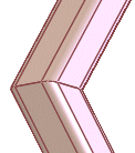
Apply corner treatment. (Available for contiguous groups only.) Defines how to trim segments of the group when they intersect at corners. You can clear Apply corner treatment and specify a corner treatment later (for example, when you trim the structural members). You can also
modify the corner treatment
, allowing you to specify multiple corner treatments per group.
|
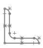
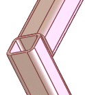
End Miter 
|
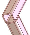
End Butt1 
|
End Butt2 
|
|
|
|
|
Merge miter trimmed bodies. (Available when you select Apply corner treatment and click End Miter .) Combines weld member bodies so that the length of the resulting weld member body in the weldment cut list is equal to the sum of the maximum lengths of the uncut weld member bodies.
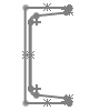
Gap between Connected Segments in Same Group  . (Available for contiguous groups only.) Specify the weld gap at the corners of segments in the same group.
Gap between Different Group Segments  . Specify the weld gap where the ends of this group's segments abut segments in another group.
Specifying a weld gap shortens segment lengths, as reflected in the cut list, and retains the overall extent of each segment.
Allow protrusion. Allows the structural member to extend the length of the sketch. This is helpful when one structural member (A) is used to trim another member (B), but A does not fully cut B. It allows the portion of B that is not cut by A to extend to the length of the sketch.
Mirror Profile. Flips the profile of the group about its Horizontal Axis or Vertical Axis.
Alignment. Aligns an axis of the group profile to any selected vector (edge, construction line, etc.). Select which axis of the profile to align:
-
Horizontal axis
-
Vertical axis
Rotation Angle  . Rotates the structural member by a set number of degrees.
Locate Profile. Zooms to the profile so you can change its pierce point relative to the sketch segment. The default pierce point is the sketch origin.