Hole Table PropertyManager
Specify properties for hole tables such as templates, datums, and holes to include.
To specify properties for new hole tables:
-
Click Hole Table  (Table toolbar) or Insert, Tables, Hole Table.
-
Specify the properties described below, then click OK  .
.
Table Template
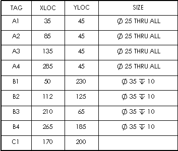
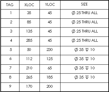
Click Browse for template  to choose a standard or custom template. This option is available only during table insertion. The hole table templates supplied with the software add columns to the default format. They are located at: install_dir\lang\english. The standard templates (standard hole table--letters.sldholtbt and standard hole table--numbers.sldholtbt) create TAG, XLOC, YLOC, and SIZE columns. One template uses letter tags, and the other uses number tags. All sizes and tags are listed separately, with none combined.
The combined hole table templates create TAG, XLOC, YLOC, and SIZE columns. They vary by combining like sizes or tags with letter or number tags. The templates are:
-
hole table--sizes combined--letters.sldholtbt
-
hole table--sizes combined--numbers.sldholtbt
-
hole table--tags combined--letters.sldholtbt
-
hole table--tags combined-numbers.sldholtbt
Table Position
Attach to anchor point. Attaches the specified corner to the table anchor.
Alpha/Numerical Control
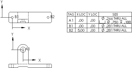
Specify the tags identifying the holes to be alphanumeric (A, B, C...) or numeric (1, 2, 3...). With alphanumeric tags, the letter prefix designates a specific hole size and the number designates an instance. Use Start at to specify a beginning letter or number.
The corresponding notes in the view change with the table.
|

|

|
|
A, B, C...
|
1, 2, 3...
|
Datum
During insertion, Origin is ready for you to select a vertex. To define the origin with an X axis and Y axis, click X Axis Direction Reference and select a horizontal model edge in the graphics area, then click Y Axis Direction Reference and select a vertical model edge.
After the table has been created, you can drag the datum origin to another position, or you can edit the datum definition. The location values in the table update.
Holes
Select individual hole edges, or select a model face to include all the holes in the face.
Border
Click Box Border  or Grid Border
  and select a corresponding border thickness from the list.
Table with thicker box and grid borders:

Next View
This option is available only during table insertion. It allows you to set the Datum and Holes for another drawing view. One hole table can include several drawing views. The hole table is added with one datum for each view. The labels are the same across all views.
