Consider these guidelines when you export from SolidWorks.
Feature Names
When scanning the components in an assembly, CircuitWorks uses the SolidWorks feature names to identify what type of ECAD geometry each represents. The names CircuitWorks uses for features are defined by the
CAD Feature Name
option. To see how CircuitWorks uses these names when exporting, look at how features are named in an assembly it has created from an IDF or PADS file. If you adopt the same conventions when creating an assembly manually, then CircuitWorks can export it back out of SolidWorks.
For example, the SolidWorks FeatureManager design tree for a PCB that was originally created by CircuitWorks shows three features: the board outline extrude called BOARD_OUTLINE and two cut-extrude features for the non-plated and plated holes called NPTH and PTH, respectively. To add an extra outline (a cut-out) to the board, you could either modify the sketch under the original BOARD_OUTLINE extrusion, or add a new cut-extrude feature. If the name of the feature includes the name CircuitWorks uses to identify board outlines, then CircuitWorks uses the information in the sketch. The names are not case-sensitive.
It is personal preference whether you define all features of one type (such as plated holes or route outlines) in one sketch, or whether you use multiple sketches. Only electrical components must have only one closed feature per sketch. All other features can have more than one outline per sketch.
You should also name keep-outs and outlines to include the import feature names. See
CircuitWorks Options - Features
. Examples are:
-
Route_Outline1
- Route_Outline _1
- Place_Keepout_one
- Via_Keepout01
- Via_Keepout_top
Sketch Names
If CircuitWorks cannot find a suitably named extrude feature in a component, then it looks at the sketch names.
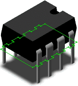
For example, a component called TO237 has an extrusion named COMPONENT_OUTLINE so is recognized by SolidWorks as an electrical component. A component called FIDMARK2 consists only of a sketch called COMPONENT_OUTLINE and is also recognized as an electrical component. However, because the sketch is named FIDMARK2 and there is no extrusion feature, this component is regarded as 2D (zero height). Because the 3D extrusion feature is named in TO237, CircuitWorks can get a height for this component.
It is recommended that you name extrude features rather than sketches when exporting so CircuitWorks can export height information.
Feature Heights
If you model ECAD features (such as components, boards, keep-outs, and outlines) as 2D sketches, then CircuitWorks exports them with zero height. However, if you extrude them to a height in SolidWorks and then export them, CircuitWorks uses the height of the extrude as the height of the ECAD feature. If features are brought into CircuitWorks as zero height unintentionally, you can add height manually in CircuitWorks if required. CircuitWorks shows zero-height geometry in the preview image as wireframes.
Because IDF 2.0 and IDF 3.0 do not support negative offsets, CircuitWorks ignores component height below the board surface. For example, if a 20mm component is pushed 5mm into the board, CircuitWorks regards the component height as 15mm with zero offset.
Geometry with Incorrect Sketches
Component sketches must be on the same plane as or planes parallel
to the board outline
sketch. If a component has a sketch in the wrong plane or it does not represent the component outline, then CircuitWorks might produce undesirable results. The solution is to create a new sketch in the SolidWorks component part for CircuitWorks to use that represents the component outline. You can hide this sketch in SolidWorks. CircuitWorks processes hidden features but not suppressed features.
For example, because of how the SolidWorks model shown has been constructed, no single sketch represents this component outline. Rather than rename an existing sketch or change the way the component has been modeled, a new sketch has been inserted into the component that represents the outline. The sketch was constructed by converting existing entities, so will change if the shape of the component changes. This sketch is named Component_Outline so that CircuitWorks treats it as the outline of the component. The sketch is shown here but would normally be hidden.
Geometry with No Sketches
A model can exist in SolidWorks with no suitable sketch to represent the feature outline, such as a part imported from another CAD system. If there is no sketch, CircuitWorks can use silhouette edges to determine component shape as follows:
-
For the board component:
-
The external silhouette edge becomes the board outline.
- Noncircular internal closed edges become board cut-outs.
- Circular holes become non-plated holes.
- For all components on the board, external silhouette edges become the feature outlines. CircuitWorks does not consider internal edges because IDF 2.0 and 3.0 do not support components with cut-outs.
If these silhouette rules produce incorrect results, create sketches. For example, create sketches for plated holes.
To control whether CircuitWorks uses silhouette edges to determine component shape, see CircuitWorks Options - SolidWorks Export.