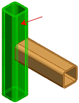
Bodies to be Trimmed
For End Miter, End Butt1, and End Butt2 corner types, select one body to be trimmed.
For End Trim corner type, select one or more bodies to be trimmed.
|
| Allow extension |
If the segment does not meet the trimming boundary, lengthens the segment to its boundary.

|
Trimming Boundary
Select a trimming boundary type (for End Trim corner type only):
| |
Face / Plane |
Use a planar face as a trimming boundary. |
| |
Bodies |
Use a body as a trimming boundary. |
| |
Selecting Face / Plane as the Trimming Boundary is normally more efficient and offers better performance. Select Bodies only when trimming against a non-planar entity such as a round pipe or a stepped surface.
|
| |
Face/Bodies |
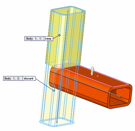
For End Miter, End Butt1, and End Butt2 corner types, select an adjacent segment to trim against. For End Trim corner type, select one or more adjacent faces or bodies to trim against. If you select Face / Plane for Trimming Boundary, toggle keep or discard to choose which segments to keep.
|
| |

|
| |
Preview |
Select to preview the trim in the graphics area. For performance reasons, disable this option for complex structures until you have selected all the items to trim. |
| |
Allow extension |
Select to allow structural members to be extended or trimmed. Clear to allow only trimming. When using this option, check the preview carefully to ensure that the results are correct. |
 |
Simple cut between bodies |
Makes the structural members flush with the planar contact faces (helpful for manufacturing). |
 |
Coped cut between bodies |
Trims the structural member to the contact body. |
| |
Weld gap |
Select this option, then enter the Weld trim gap  to allow space for a weld bead. The gap reduces the length of the trimmed item, retaining the overall length of the structure. to allow space for a weld bead. The gap reduces the length of the trimmed item, retaining the overall length of the structure.
|
| |
Callouts |
If the trimming boundary intersects the item to trim, callouts appear next to trimmed segments with a body identifier and a toggle for keeping or discarding the segment. |
If you trim with a plane or a face and keep all pieces, the pieces are cut. If you discard any of the pieces, the remaining adjacent pieces are combined.