For shell models, symmetry requires that faces coinciding with planes of symmetry should be prevented from moving in the normal direction and rotating about the other two orthogonal directions. The planes of symmetry should be orthogonal to each other.
For surface geometries, symmetry restraints are applied on the faces coinciding with the planes of symmetry of the model along the model thickness.
Use the Symmetry fixture under Advanced in the Fixture PropertyManager to apply a symmetry restraint to shell faces or shell edges. The shell edges must be planar. The shell faces must lie on orthogonal planes of symmetry.
Symmetry requires that geometry, restraints, loads, and material properties are symmetrical. In general, using symmetry is not recommended for buckling and frequency studies.
The following examples explain how symmetry restraints are applied to the different geometries:
Sheet Metals that Mesh with Shell Elements
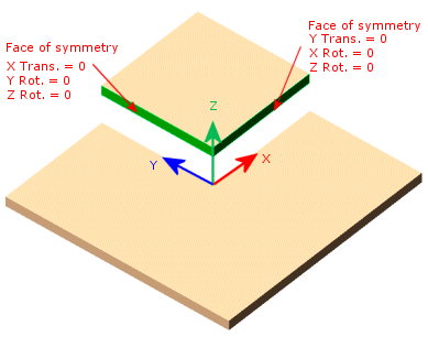
Planar Symmetry

Lets assume this model is symmetric about two planes. You can analyze a quarter of the model. The Symmetry restraint automatically applies the translation and rotation conditions to the selected faces.
The faces must be orthogonal to each other.
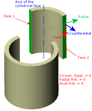
Axial Symmetry

This model is axisymmetric. You can analyze half or one quarter of the model. The Symmetry restraint automatically applies the translation and rotation conditions to the selected faces.
Surfaces
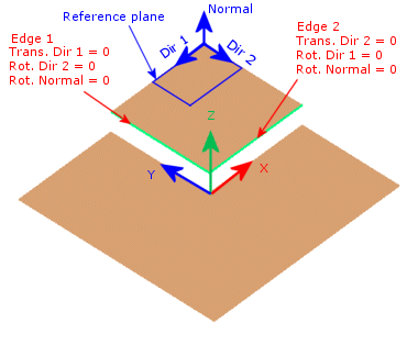
Planar Symmetry

This surface model is symmetric about two planes. You can analyze a quarter of the model. Apply a Symmetry restraint to the shell edges. The selected edges must be orthogonal to each other.
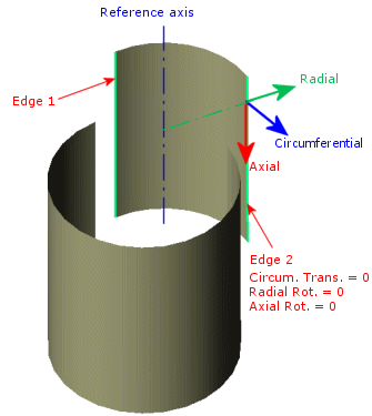
Axial Symmetry

This surface model is axisymmetric. You can analyze half or one quarter of the model. Apply a Symmetry restraint to the shell edges.