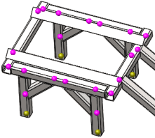
A joint is identified at the free end of a structural member or at the intersection of two or more structural members.
Selected Beams
| All |
The software considers all structural members when calculating joints.
|
| Select |
The software considers only the structural members in Select structural members  when calculating joints. when calculating joints.
|
| Calculate |
Click to calculate the joints.
The software highlights with pink color  the joints where two or more structural members intersect, and with light green color the joints where two or more structural members intersect, and with light green color  the joints of a structural member at its free ends. the joints of a structural member at its free ends.

The program treats touching, interfering and non-touching structural members within a tolerance automatically as beams and calculates the joints. However extrusions that are solids can be treated as beams if desired (Right-click the Solid icon and select Treat as Beam). For extrusions that are treated as beams, the program does not automatically calculate joints.
|
Results
Lists the joints that the software finds in the model. Select a joint from the list to highlight it in the graphics area.
Pink joints are highlighted with orange  , and light green joints with a bright green color
  .
.
Right-click a joint in the graphics area to list the structural members that make up the joint in the Select Joint Members box.
To modify a joint, right-click it in the graphics area to highlight the members that make up the joint. To add a member, select a member that is not highlighted. To delete a member from the joint, select the highlighted member in the graphics area. The selected member disappears from the Select Joint Members box.
| Delete |
Click to delete a joint from the list. |
| Keep modified joint on update |
Select to save your modifications when you click Calculate to update the joints. |
| Display neutral axis |
Select to view the neutral axis of each beam. |
| Display shear center |
Select to view the shear center axis of each beam. The axis that connects all shear centers across the beam length is colored red in the graphics area. The shear center of a beam's cross section is that point through which when a lateral load is applied, it causes only bending of the section and no twisting. For a beam cross section with two axes of symmetry, the shear center coincides with the centroid of the section.
|
Criteria
For non-touching structural members within a certain distance (tolerance), the software computes an optimal tolerance value, but the user can overwrite it.
Treat as joint for clearance less than. Select this option to overwrite the optimal tolerance value. Type a value and select units for tolerance.