Automatically create solids based on the desired amount of detail.
Whenever possible, the result is a solid. If the surfaces cannot be knitted together, the result is a surface.
 |
 |
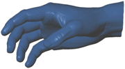
| Mesh
|
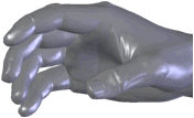
Surface created from mesh
|
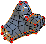
Surfaces created by ScanTo3D are composed of patches (ideally four-sided). Groups of patches form regions on the surfaces. Feature lines form the boundaries between regions.
| Feature lines = orange
Patch boundaries = black
Ends of feature lines = red circles
|
 |
Ideally, feature lines are located where the mesh curvature transitions between a contact through tangent relationship. For example, at a filleted edge separating two sides of a cube.
You can edit feature lines in the Automatic Surface Creation PropertyManager to extract more desirable surfaces. You can create and delete lines plus move lines and vertices.
To automatically create solids:
- Move the slider to set the amount of Surface Detail.
Moving the slider left makes bigger patches, increases generation speed, but creates surfaces with less detail. Moving the slider right makes smaller patches, decreases generation speed, but creates surfaces with greater detail and accuracy.
- Click Update Preview.
ScanTo3D creates surfaces from the mesh. The graphics area updates and the PropertyManager reports the Number of surfaces.
- To modify the number of surfaces, re-position the slider, then click Update Preview. Repeat as necessary to achieve the desired results.
- To edit feature lines, select Edit feature lines and use the editing tools.
- Edit feature lines. Displays feature lines and enables these editing tools:
- Show patch boundaries. Toggles the display of patch boundaries only.
- Click
 .
.ScanTo3D creates surfaces, then knits them together to form a solid model.