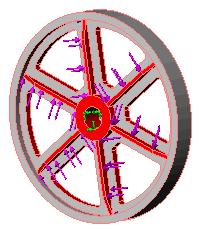
Circular symmetry allows you to analyze a model with circular patterns around an axis by modeling a representative segment. The segment can be a part or an assembly . The geometry, restraints, and loading conditions must be similar for all other segments making up the model. Turbine, fans, flywheels, and motor rotors can usually be analyzed using circular symmetry.
The Circular Symmetry restraint can be applied for a solid model and for a static study only. You define it for two sections, and you need to define the axis of revolution for the symmetry.
| Attribute |
Value |
|---|
| Selectable entities
|
Two sets of faces. Each set represents one side. The faces should be similar and can be non-planar. The areas of the faces in the two sets must be similar.
|
| Translations
|
The program enforces equal translations at each pair of nodes with similar relative positions on the two sections.
|
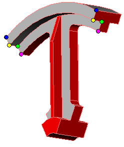
Nodes on opposite sections with similar relative positions displace similarly. For example, locations with similar color of dots in the figure deform similarly.

Example
 |
 |
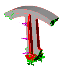
| You model one sixth of the wheel and apply circular symmetry to the cut faces.
|