The Drop Test Setup PropertyManager sets parameters for a drop test study.
To access this PropertyManager, create a drop test study. In the drop test study tree, double click Setup.
Specify
Sets the type of input you will specify.
| Drop height |
You specify the height from which the model is dropped from rest.
|
| Velocity at impact |
You specify the direction and magnitude of the model's velocity at the moment of impact with the target plane.
|
Height
Sets the height from which the body is dropped from rest. This is the distance that the body has to travel in the direction of gravity to hit the rigid plane. Available only when you select Drop height in the Specify box. The velocity at impact is calculated from Vimpact = (2gh)½, where g is the acceleration of gravity, and h is the height.
| |
From centroid |
The specified height is the distance between the centroid of the body and the planar rigid floor in the direction of gravity.
The centroid is the geometric center of the body. For an assembly, the centroid coincides with the center of gravity only if all components have the same density.
|
| |
From lowest point |
The specified height is the smallest distance between the body and the rigid planar floor. The closest point to the rigid planar floor is the first the point to hit the floor as the body travels in the direction of the gravity.
|
 |
Drop height |
Specifies height from centroid or from lowest point to the impact plane. You can select units for height.
|
Velocity at Impact
Sets the direction and value of the velocity at the time of impact. Used only if you select Velocity at impact in the Specify box.
| |
Impact velocity reference |
Sets the reference entity to determine the direction of the velocity at impact. You can select an edge, a reference plane, or planar face. If you select a reference plane or planar face, the velocity is applied in the direction normal to the reference plane or the planar face. Click  to reverse the direction of the velocity at impact. to reverse the direction of the velocity at impact.
|
 |
Velocity magnitude |
Sets the magnitude and unit of the velocity at impact.
|
Gravity
Sets the direction and value of the acceleration of gravity.
| |
Gravity reference |
Sets the reference entity to determine the direction of the gravity. You select an edge, a reference plane, or planar face. If you select a reference plane or planar face, the gravity is applied in the direction normal to the reference plane or the planar face. Click to reverse the direction of gravity.
|
 |
Gravity magnitude |
Sets the magnitude and unit of the gravity.
|
Target
Sets the orientation of the impact plane.
| Target Orientation |
|
|
| |
Normal to gravity |
The impact plane is normal to gravity.
|
| |
Parallel to Ref. plane |
The impact plane is parallel to the selected reference plane.
|
 |
Target orientation reference |
Select a reference plane. Available only when Parallel to ref. plane is selected.
|
 |
Friction Coefficient |
Sets the coefficient of friction between the model and the impact plane.
The program determines the actual position of the impact plane as follows:
- If you specified the Height, the body hits the plane after traveling the specified height distance in the direction of gravity.
- If you specified the Velocity at impact, the body hits the plane while traveling in the specified velocity at impact.
 |
 |
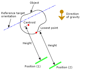
Actual location of the impact plane if the height is specified.
Position (1): Height is measured from the body centroid.
Position (2): Height is measured from lowest point of the body.
|
Actual location of the impact plane if velocity at impact is specified
|
|
| Target Stiffness |
|
|
| |
Rigid target |
Use rigid plane for target.
|
| |
Flexible target |
Use flexible layer for target.
|
Contact Damping
Contact damping is considered for bodies that come into contact with each other during impact and have No penetration contact between them. Contact damping is calculated as viscous damping. The input is a damping value as a ratio of the critical damping (ζcr = 2* m* ω).
 |
Critical Damping Ratio |
Damping value as a ratio of critical damping (ζcr = 2* m* ω). For example, to apply 5% critical damping, enter 0.05.The application of contact damping reduces the high frequency oscillations that may occur during impact and improves the solution stability (Drop Test Setup PropertyManager).
|
Symbol Settings
Shows the directions of acceleration of gravity and the velocity at impact.
| |
Edit Color |
Click this button to change the color of the velocity and the acceleration symbols.
|
 |
Symbol Size |
Controls the size of the velocity and acceleration symbols.
|
| |
Show Preview |
Shows preview of symbols on the graphics window.
|