Hide Table of Contents

Automatic Surface Creation PropertyManager

Automatically create solids based on the desired amount of detail.

Whenever possible, the result is a solid. If the surfaces cannot be knitted together, the result is a surface.
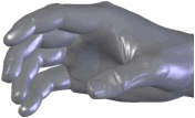
Hand_Mesh.gif Hand_Solid.gif
Mesh Surface created from mesh
Surfaces created by ScanTo3D are composed of patches (ideally four-sided). Groups of patches form regions on the surfaces. Feature lines form the boundaries between regions.
Feature lines = orange

Patch boundaries = black

Ends of feature lines = red circles

AutoSurf_FeaLinesAndPatches.gif

Ideally, feature lines are located where the mesh curvature transitions between a contact through tangent relationship. For example, at a filleted edge separating two sides of a cube.

You can edit feature lines in the Automatic Surface Creation PropertyManager to extract more desirable surfaces. You can create and delete lines plus move lines and vertices.

To automatically create solids:

  1. Move the slider to set the amount of Surface Detail.

    Moving the slider left makes bigger patches, increases generation speed, but creates surfaces with less detail. Moving the slider right makes smaller patches, decreases generation speed, but creates surfaces with greater detail and accuracy.

  2. Click Update Preview.

    ScanTo3D creates surfaces from the mesh. The graphics area updates and the PropertyManager reports the Number of surfaces.

  3. To modify the number of surfaces, re-position the slider, then click Update Preview. Repeat as necessary to achieve the desired results.
  4. To edit feature lines, select Edit feature lines and use the editing tools.

    • Edit feature lines. Displays feature lines and enables these editing tools:
      Tool_Add_Feature_Lines_ScanTo3D.gif Add Feature Lines Red points and a green circle RedPt_GreenCircle.gif indicate valid start and end points for new feature lines.
      A new feature line cannot intersect an existing feature line.
      Video: Adding Feature Lines
      Tool_Delete_Feature_Lines_ScanTo3D.gif Delete Feature Lines   Video: Deleting Feature Lines
      Tool_Move_Feature_Lines_By_Ends_ScanTo3D.gif Move Feature Lines By Ends Move the pointer over a vertex, then drag to re-position the vertex and feature lines. Video: Moving Feature Lines By Ends
      Tool_Relax_Feature_Lines_ScanTo3D.gif Relax Feature Lines Creates a smoother boundary between regions. Relaxing feature lines the first time does not always generate visible results. Relaxing a feature multiple times usually produces visible changes. Video: Relaxing Feature Lines
    • Show patch boundaries. Toggles the display of patch boundaries only.

  5. Click PM_next.gif.

    ScanTo3D creates surfaces, then knits them together to form a solid model.


Provide feedback on this topic

SOLIDWORKS welcomes your feedback concerning the presentation, accuracy, and thoroughness of the documentation. Use the form below to send your comments and suggestions about this topic directly to our documentation team. The documentation team cannot answer technical support questions. Click here for information about technical support.

* Required

 
*Email:  
Subject:   Feedback on Help Topics
Page:   Automatic Surface Creation PropertyManager
*Comment:  
*   I acknowledge I have read and I hereby accept the privacy policy under which my Personal Data will be used by Dassault Systèmes

Print Topic

Select the scope of content to print:

x

We have detected you are using a browser version older than Internet Explorer 7. For optimized display, we suggest upgrading your browser to Internet Explorer 7 or newer.

 Never show this message again
x

Web Help Content Version: SOLIDWORKS 2014 SP05

To disable Web help from within SOLIDWORKS and use local help instead, click Help > Use SOLIDWORKS Web Help.

To report problems encountered with the Web help interface and search, contact your local support representative. To provide feedback on individual help topics, use the “Feedback on this topic” link on the individual topic page.