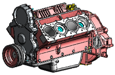
SpeedPak creates a simplified configuration of an assembly without losing references. If you work with very large and complex assemblies, using a SpeedPak configuration can significantly improve performance while working in the assembly and its drawing.
Improvements in assembly performance are most noticeable in very large and complex assemblies.
A SpeedPak configuration is essentially a subset of the parts and faces of an assembly. Unlike regular configurations, where you can simplify an assembly only by suppressing components, SpeedPak simplifies without suppressing. Therefore, you can substitute a SpeedPak configuration for the full assembly in higher level assemblies without losing references. Because only a subset of the parts and faces is used, memory usage is reduced, which can increase performance of many operations.
When you make changes to an assembly, such as adding, deleting, or moving components, the changes are not automatically incorporated into the SpeedPak configuration, even when you rebuild the assembly. You must manually
update the SpeedPak configuration to incorporate the changes.
When to Use SpeedPak
Use SpeedPak when you want to insert a complex large assembly into a higher level assembly, especially if you want to see the entire SpeedPak assembly, but need to mate and dimension only to relatively few locations.
You can also use SpeedPak to facilitate file sharing. The SpeedPak information is saved entirely within the assembly file. Therefore, when sharing an assembly, you can send just the assembly file. You do not need to include component files.
For example, suppose you design an engine assembly, and need to send it to your customer's design team so they can insert it in their vehicle design.
-
You create a SpeedPak configuration of the engine assembly, including all the faces and bodies your customer plans to reference in their vehicle model.
- You send them just the engine assembly file. You do not need to send files for any of the engine component parts.
- They insert your engine assembly file into their vehicle assembly file. They can add mates and dimensions to all faces and bodies you included in the SpeedPak definition.
|
 |
SpeedPak in Drawings
|
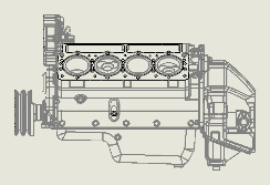
When you dimension SpeedPak configurations in drawings, you can only dimension to edges included in the SpeedPak, which are shown in black. Edges not included in the SpeedPak are shown in gray. When you print the drawing, all the lines print in black, unless you select Color / Gray scale in the Page Setup dialog box.
|
 |
In a drawing document, when you create a bill of materials for an assembly whose active configuration is a SpeedPak configuration, you can include columns for other configurations in addition to the SpeedPak configuration.
In an assembly document, when you create a bill of materials for an assembly whose active configuration is a SpeedPak configuration, you can include only the active SpeedPak configuration in the BOM.
You can use Balloon  (Annotations toolbar) to add balloons to all items in a SpeedPak assembly, but the Auto Balloon command is not supported.