The Stress Hot Spot diagnostics tool detects regions of the model where stress gradients between adjacent elements are very high. In certain cases, these high stress gradients can be attributed to stress singularities.
The Stress Hot Spot functionality is only available with linear static studies that use solid and shell mesh elements.
The stress hot spot diagnostic tool can help you identify regions of the model that are susceptible to stress singularities by detecting irregular high stress gradients between adjacent elements.
The concept of a stress singularity exists in numerical analysis, and does not have a physical meaning, as there are no infinite stresses at a singular point.
The stress hot spot diagnostics tool detects stress singularities in a model in these cases:
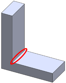
- Near sharp geometric edges and internal reentrant corners on solid and shell bodies.
 |
 |
| (a) Stress singularities detected at sharp edges where no fillets are applied. The angle between the geometric planes at the common sharp edges ranges from 0º -180º. |
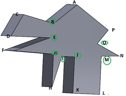
(b) The stress hot spot diagnostics tool detects stress singularities at the internal corners which are encircled in green. These corners are located on angles ranging from 0º -180º. |
- At regions where applied boundary conditions restrict the body to freely expand (or contract) under the loading environment. Remember that in the real world there are no "infinitely stiff" supports or fixtures.
- On geometric edges of solids where loads/fixtures are applied, or where abrupt transitions of boundary conditions occur (very rigid to flexible).
- Around vertices where point loads and point fixtures are applied (on solids or shells).
Stress hot spots are not detected at areas of contact and at faces where rigid fixtures are applied.
To open the Stress Hot Spot diagnostics:
- Right-click the Results
 folder, and click Stress Hot Spot Diagnostics.
| |
Sensitivity Factor |
Filters the elements that participate in the stress hot spot diagnosis based on the magnitude of the equivalent strain relative to the maximum equivalent strain for each body. A higher sensitivity factor includes more elements with high strains, and may detect multiple stress hot spot areas on multiple bodies (at the expense of longer computational time).
For example, for a sensitivity factor of 60%, the tool includes elements that fall within the top 60% of highest equivalent strains for each body.
|
| |
Node Values |
When selected, you can view the stress hot spots on contour plots of nodal or elemental Von Mises stresses. Elemental plots display one stress value for each element. Nodal plots display one stress value for each node. |
| |
Run Stress Hot Spot Diagnosis
|
Executes the stress hot spot diagnostics tool. If stress hot spots are detected, in the next step you can view a von Mises contour plot with the hot spot areas colored in gray. You can select a different color from the default gray to render the stress hot spots in the . You cannot modify the maximum threshold stress value shown on the chart of a Stress Hot Spot plot. Regions of the model with stress values higher than the maximum threshold stress value are highlighted in gray and flagged as stress hot spots by the solver.
|
| |
Show/Hide Stress Hot Spots
|
Toggles the visibility of the stress hot spots on the von Mises contour plot. |
| |
Isolate Stress Hot Spots
|
Renders only the stress hot spot areas on the model which is shown in transparent mode.
In the plot legend you can view the sensitivity factor considered for the analysis, the number of elements flagged as stress hot spots, and the percentage of elements flagged as stress hot spots.
|
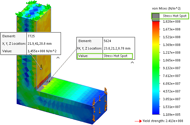 |
| Stress hot spots are detected and highlighted in gray. Probed annotations on elements display the Stress Hot Spot string for Value. |