Usually you specify dimensions when you design a part, then insert the dimensions from the model into the drawing. Changing a dimension in one document changes it in any associated documents.
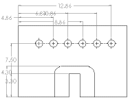
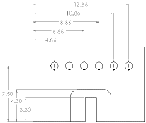
The Auto Arrange Dimensions  tool positions dimensions quickly and easily.
 |
 |
| Before |
After |
You can set an option during installation of SOLIDWORKS that prevents changes in dimensions in drawings from affecting part or assembly models.
You can use magnetic lines to align balloons. You can automatically insert center marks for all holes, fillets, and slots in drawing views.
In SOLIDWORKS, dimension formatting follows the standard that is set for the document in by default. You can change the document or template defaults for each type of dimension listed under . Both 2D CAD software and SOLIDWORKS software use styles to save particular formatting.
2D CAD systems have a type of dimension which is comparable to reference dimensions in SOLIDWORKS. Reference dimensions cannot be modified and do not change model geometry. However, when a model changes, reference dimensions update automatically. Model dimensions are linked to the model parametrically, using dimension names, and, when changed (in drawings or in model documents), modify the model.
When you insert dimensions in part and assembly documents, they are marked for drawings unless you specify otherwise. When you insert model dimensions with Model Items, automatically for a new drawing view, or with Autodimension, only the dimensions marked for drawings are inserted. When you insert an annotation view into a drawing, all annotations in the part or assembly are inserted in the drawing.
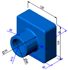
| Dimensions define the geometry in the model sketches. |
 |
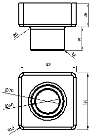
| The model dimensions are transferred into the drawing using .
|
 |
Baseline dimensions, ordinate dimensions, chamfer dimensions, and hole callouts are available in drawings. Ordinate dimensions are also available in sketches.
| Baseline dimensions |
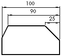 |
| Ordinate dimensions |
 |
| Chamfer dimensions |
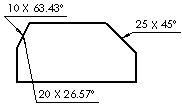 |
| Hole callout |
 |