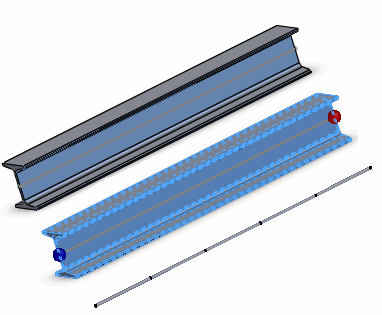
When you create a straight beam, the software automatically creates a coordinate system for it. This system defines the axial direction as well as directions 1 and 2 that are used for viewing beam results. The axial direction goes from End 1

of the beam to End 2

. Directions 1 and 2 are assigned by the software automatically depending on the section properties. A number of beam elements are created on the beam.
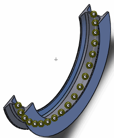
For curved profiles, the software creates a number of short straight beams to approximate the geometry. Each beam element has its own directions. For example, the axial direction for each beam on the swept section shown below is defined by the straight line connecting its two joints. In the graphics area, one coordinate system is shown at the middle of the beam.