Expand IntroductionIntroduction
Expand AdministrationAdministration
Expand User InterfaceUser Interface
Expand SOLIDWORKS FundamentalsSOLIDWORKS Fundamentals
Expand Moving from 2D to 3DMoving from 2D to 3D
Expand AssembliesAssemblies
Expand CircuitWorksCircuitWorks
Expand ConfigurationsConfigurations
Expand SOLIDWORKS CostingSOLIDWORKS Costing
Expand Design CheckerDesign Checker
Expand Design Studies in SOLIDWORKSDesign Studies in SOLIDWORKS
Expand Detailing and DrawingsDetailing and Drawings
Expand DFMXpressDFMXpress
Expand DriveWorksXpressDriveWorksXpress
Expand FloXpressFloXpress
Expand SLDXML Data ExchangeSLDXML Data Exchange
Expand Import and ExportImport and Export
Expand Model DisplayModel Display
Expand Mold DesignMold Design
Expand Motion StudiesMotion Studies
Collapse Parts and FeaturesParts and Features
Expand RoutingRouting
Expand Sheet MetalSheet Metal
Expand SimulationSimulation
Expand SimulationXpressSimulationXpress
Expand SketchingSketching
Expand SOLIDWORKS MBDSOLIDWORKS MBD
Expand SOLIDWORKS UtilitiesSOLIDWORKS Utilities
Expand SOLIDWORKS SustainabilitySOLIDWORKS Sustainability
Expand TolerancingTolerancing
Expand TolAnalystTolAnalyst
Expand ToolboxToolbox
Expand WeldmentsWeldments
Expand Workgroup PDMWorkgroup PDM
Expand TroubleshootingTroubleshooting
Glossary
Hide Table of Contents

Interactive Feature Recognition Selections

Standard Feature Types

Feature type Selected entities Required selection Example
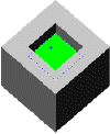
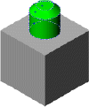
Boss Extrude or Cut Extrude Face Select a model face representing the sketch for the feature.

For all extrudes, FeatureWorks recognizes the Blind end condition. For cut-extrudes, FeatureWorks also recognizes Through All and Up to Next.

FWORKS3.gif
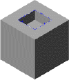
Boss Extrude or Cut Extrude Edges or Loop Select the complete set of edges, or the loop, representing the sketch for the feature. FWORKS4.gif
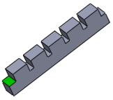
Boss Extrude or Cut Extrude Parallel faces Select a planar face that defines an extrude and select Check parallel faces. FW-boss-extrude-parallel-faces1.gif
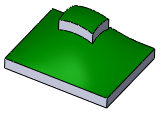
Boss Extrude or Cut Extrude Non-Planar faces Select the non-planar face of the boss extrude, then select the non-planar supporting face in the Up to face box. The boss extrude must be an exact offset from the supporting face. FWORKS17.gif
Boss Extrude or Cut Extrude Non-Planar faces Select the non-planar face of the cut extrude, then select the non-planar supporting face in the Up to face box. The cut extrude must be an exact offset from the supporting face. FWORKS18.gif
Boss Revolve or Cut Revolve Face Select the complete set of faces representing the sketch for the revolve feature.

If the Chain revolved faces check box is selected, select a single face for this revolve. The FeatureWorks software selects the chained faces.

FWORKS7.gif
Cut Revolve Face Select the face of the cut revolved feature, and verify that Chain revolved faces is cleared. FWORKS19.gif
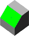
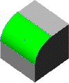
Chamfer Face Select a model face representing the chamfered face. FWORKS6.gif
Draft Face Select the drafted faces and a face representing the neutral plane. FWORKS12.gif
Fillet/Round Face Select a model face representing the filleted face. FWORKS5.gif
Fillet/Round Face Select a variable radius fillet. FW_var_rad_fillet.gif
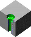
Hole Face Select the complete set of faces representing the sketch for the hole feature. FeatureWorks recognizes Hole Wizard holes.

FeatureWorks recognizes these end conditions: Blind, Through All, and Up to Next. FeatureWorks also recognizes these end conditions when you use the resize tool.

FWORKS8.gif
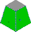
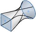
Base-Loft Face Select an End Face 1 and End Face 2. Loft.gif
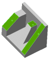
Rib Face Select a face unique to the rib. FWORKS14.gif
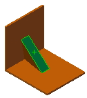
Rib Face Recognize ribs that are extruded using Normal to Sketch as the Extrusion direction.

Select the face (on the rib) that was used to create the normal to sketch rib.

FW_rib_normal.gif
Rib Face Recognize ribs that include a negative draft.

Select a face unique to the rib.

FWORKS16.gif
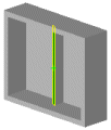
Shell Face Select the face at the end of the shell feature. Only shell features with uniform thickness can be recognized. Only shell features created with an inward shell can be recognized. FW_shell.gif
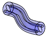
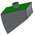
Boss Sweep or Cut Sweep Face Select the face at one end of th sweep under End Face 1, and select the face at the other end under Select Face 2 sweep_internal_loops.gif
Boss Sweep or Cut Sweep Face Select the face on the upper boss for End Face 1 and select the supporting face of the boss for End Face 2/Support Face. FWORKS20.gif
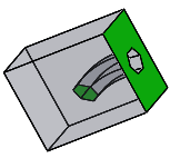
Boss Sweep or Cut Sweep Face Select the face with the opening as End Face 1 and select the other end of the sweep as End Face 2. FWORKS21.gif
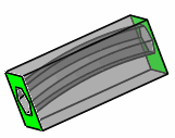
Boss Sweep or Cut Sweep Face Select the face at one end of the sweep as End Face 1 and select the face at the other end of the sweep as End Face 2. FW-cut-sweep-thruall1.gif
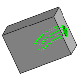
Boss Sweep or Cut Sweep Face Under Cut faces, select the faces of the sweep. FW-cut-sweep-blind-faces.gif

Sheet Metal Feature Types

Feature type Selected entities Required selection Example
Base Flange Face Select any one of the base flange faces. FW_sheetmetal_base.gif
Sketched Bend Fixed face Select the fixed face along which the part was bent. Sharp bends cannot be recognized. FW_sheetmetal_bend.gif
Hem Face Select the hem face or the bend face. Hem.gif
Edge Flange Face Select any one of the edge flange faces. EdgeFlange.gif
Miter Flange Face Select the inner or outer flange face of the miter flange that meets the fixed face. You can recognize miter flanges with offset or on multiple edges. Miter flange recognition has limitations. FW_sheetmetal_miterflange.gif


Provide feedback on this topic

SOLIDWORKS welcomes your feedback concerning the presentation, accuracy, and thoroughness of the documentation. Use the form below to send your comments and suggestions about this topic directly to our documentation team. The documentation team cannot answer technical support questions. Click here for information about technical support.

* Required

 
*Email:  
Subject:   Feedback on Help Topics
Page:   Interactive Feature Recognition Selections
*Comment:  
*   I acknowledge I have read and I hereby accept the privacy policy under which my Personal Data will be used by Dassault Systèmes

Print Topic

Select the scope of content to print:

x

We have detected you are using a browser version older than Internet Explorer 7. For optimized display, we suggest upgrading your browser to Internet Explorer 7 or newer.

 Never show this message again
x

Web Help Content Version: SOLIDWORKS 2017 SP05

To disable Web help from within SOLIDWORKS and use local help instead, click Help > Use SOLIDWORKS Web Help.

To report problems encountered with the Web help interface and search, contact your local support representative. To provide feedback on individual help topics, use the “Feedback on this topic” link on the individual topic page.