SOLIDWORKS can create complex shapes not supported by IDF. To ensure your geometry exports correctly, review the following topics.
Closed Profiles
IDF expects features to be defined as closed profiles (an unbroken chain of entities). All features to be exported should conform to this rule. A good test is to extrude your sketches in SOLIDWORKS. If a sketch extrudes correctly, then it should be suitable for export.
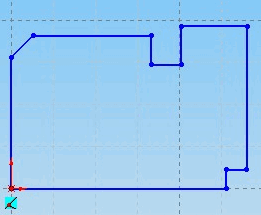
Example: Closed Profile

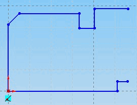
Example: Open Profile

Number of Profiles / Loops per Sketch
IDF 2.0 and 3.0 files support only one closed profile per electrical component. A sketch defining an electrical component must consist of only one unbroken chain of entities. Sketches with more than one profile (loop) per sketch do not export correctly as electrical components. If the sketches used to create your component model are complex, consider simplifying the shape of your component model, converting surplus sketch entities to construction geometry (which is ignored by CircuitWorks), or creating a specific “footprint sketch” for use when exporting a component. Other IDF features can have more than one closed profile. For example, a board outline sketch can contain more than one sketch loop to represent cutouts in the board.
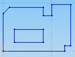
Example: This multiple loop sketch is suitable for export as a board outline, keep-out, or other outline, but not as a component.

By converting the central loop of entities to construction geometry, CircuitWorks regards this sketch as a single loop sketch, which is suitable for export as a component.

Supported Sketch Entity Types
IDF supports only straight lines and arcs. CircuitWorks attempts to convert more complex sketch geometry into a straight line or arc before exporting to IDF.
CircuitWorks supports the following SOLIDWORKS sketch entities:
- Line
- Rectangle
- Parallelogram
- Polygon
- Circle
- Arc
- Spline (approximated using straight lines, with the level of detail determined by SOLIDWORKS display settings)
CircuitWorks does
not support:
- Ellipse
- Partial Ellipse
- Parabola
- Text Sketch Entities
CircuitWorks ignores any unsupported entities. Note that if an ignored entity is part of a close profile, the result might be an open profile, which is not supported.
Construction Geometry
CircuitWorks ignores construction lines in sketches when exporting. Only geometries created from solid unbroken lines are exported.
Hidden and Suppressed Components
CircuitWorks ignores suppressed or hidden components in the FeatureManager design tree. This behavior is useful when exporting an assembly that contains features that you do not want to export. Your assembly of the board and components might also contain mechanical parts or enclosures, for example. CircuitWorks also ignores suppressed features within a component.