Linear Pattern PropertyManager

The Linear Pattern PropertyManager appears when you pattern one or more features along one or two linear paths.

To access this PropertyManager:

Click Linear Pattern (Features toolbar) or Insert > Pattern/Mirror > Linear Pattern.

Some fields that accept numeric input allow you to create an equation by entering = (equal sign) and selecting global variables, functions, and file properties from a list. See Direct Input of Equations in PropertyManagers.

Direction 1

Pattern Direction Sets the direction for the Direction 1 pattern. Select a linear edge, line, axis, dimension, planar faces and surfaces, conical faces and surfaces, circular edges, and reference planes. Click Reverse Direction to reverse the pattern direction.
Spacing and instances Independently sets the instance number and spacing.

Spacing

Sets the spacing between pattern instances for Direction 1.

Number of Instances

Sets the number of pattern instances for Direction 1. This number includes the original features or selections.

Up to reference Sets the instance number and spacing based on selected reference geometry.

Reference Geometry

Sets the reference geometry that controls the pattern.

Offset distance

Sets the distance of the last pattern instance from the reference geometry.

Reverse offset direction

Reverses the direction that the pattern is offset from the reference geometry.

Centroid

Calculates the offset distance from the reference geometry to the centroid of the patterned feature.

Selected reference

Calculates the offset distance from the reference geometry to a selected seed feature geometry reference.

Seed Reference

Sets which seed feature geometry to calculate the offset distance from.

Direction 2

Creates a pattern in a second direction.

Pattern Direction Sets the direction for the Direction 2 pattern. Select a linear edge, line, axis, dimension, planar faces and surfaces, conical faces and surfaces, circular edges, and reference planes.
Spacing and instances Independently sets the instance number and spacing.

Spacing

Sets the spacing between pattern instances for Direction 1.

Number of Instances

Sets the number of pattern instances for Direction 1. This number includes the original features or selections.

Offset from reference Sets the instance number and spacing based on selected reference geometry.

Reference Geometry

Sets the reference geometry that controls the pattern.

Offset distance

Sets the distance of the last pattern instance from the reference geometry.

Reverse offset direction

Reverses the direction that the pattern is offset from the reference geometry.

Centroid

Calculates the offset distance from the reference geometry to the centroid of the patterned feature.

Selected reference

Calculates the offset distance from the reference geometry to selected seed feature geometry.

Seed Reference

Sets which seed feature geometry the offset distance is calculated from.

Pattern seed only Creates a linear pattern in Direction 2 by using the seed features only, without replicating the pattern instances of Direction 1.
 
  Pattern seed only option selected. The seed feature only replicates in Direction 2. Pattern seed only option cleared. The entire linear pattern replicates in Direction 2.

Features to Pattern

Features to Pattern Creates the pattern by using the feature that you select as the seed feature.

Faces to Pattern

Faces to Pattern Creates the pattern by using the faces that make up the feature. Select all the faces of the feature in the graphics area. This is useful with models that import only the faces that make up the feature, and not the feature itself.
When using Faces to Pattern, the pattern must remain within the same face or boundary. It cannot cross boundaries. For example, a cut across the entire face or different levels (such as a raised edge) creates a boundary and separate faces, preventing the pattern from propagating.

Bodies to Pattern

Solid/Surface Bodies to Pattern Creates the pattern by using the bodies that you select in a multibody part.
   
    Multibody part with Body to Pattern Linear pattern applied

Instances to Skip

Instances to Skip Skips the pattern instances that you select in the graphics area when you create the pattern. The pointer changes to when you hover over each pattern instance. Click to select a pattern instance. The coordinates of the pattern instance appear. To restore a pattern instance, click the instance again.

Feature Scope

Apply features to one or more multibody parts by selecting Geometry pattern under Options, and by using Feature Scope to choose the bodies that will include the feature.
Create the model that you want to add the features for multibody parts before adding those features.
  All bodies Applies the feature to all bodies every time the feature regenerates. If you add bodies to the model that are intersected by the feature, these new bodies regenerate to include the feature.
   
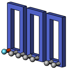
    Extrude and dome feature applied to all bodies.
  Selected bodies Applies the feature to the bodies that you select. If you add bodies to the model that are intersected by the feature, you must use Edit Feature to edit the pattern feature, select those bodies, and add them to the list of selected bodies. If you do not add the new bodies to the list of selected bodies, they remain intact.
   
    Extrude and dome features applied to selected body.
  Auto-select (Available if you click Selected bodies) When you create a model with multibody parts, the feature automatically processes all the relevant intersecting parts. Auto-select is faster than All bodies because it processes only the bodies on the initial list and does not regenerate the entire model. If you click Selected bodies and clear Auto-select, you must select the bodies in the graphics area that you want to include.
Bodies to Affect (Available if you clear Auto-select) Select the bodies to affect in the graphics area.

Options

Vary sketch Allows the pattern to change as it repeats.
Geometry pattern Creates the pattern by using only the geometry (faces and edges) of the features, rather than patterning and solving each instance of the feature. Geometry pattern speeds up the creation and rebuilding of the pattern. You cannot create geometry patterns of features that have faces merged with the rest of the part.
Propagate Visual Properties Propagates SOLIDWORKS colors, textures, and cosmetic thread data to all pattern instances.

Instances to Vary

This option is only available when you select a feature for the pattern instance.

Direction 1 Increments

Direction 1 Spacing Increments Cumulatively increments the spacing between the centers of the pattern instances in Direction 1.

For example, if the spacing between rows in the pattern is 1.5mm, and you enter .3mm for Space Increment, then the second row is positioned 1.8mm from the first, the third row is positioned 2.1mm from the second, and the fourth row is positioned 2.4mm from the third.

  Choose Feature dimensions to vary in Direction 1 Displays dimensions of the seed feature in a table. In the graphics area, click the dimensions of the seed feature to display the table. Add a value in the Increment column to increase or decrease the size of the feature dimension for Direction 1.
The same fields apply to Direction 2 Increments.

Modified Instances

Lists the individual instances that are modified. They are identified by their column and row number in the pattern.

To modify an individual instance, left-click the instance marker in the graphics area, and click Modify Instance. You can enter values to override the spacing and dimensions in the callout.

To remove a modified instance, right-click the instance in the box and click Delete. To remove all modified instances, right-click in the box and click Clear All.