You can create smart explode lines automatically for components in an
exploded view.
You can view the associated explode steps for a selected component in the Smart
Explode Lines PropertyManager. Smart explode lines use the bounding box center as a
reference point by default.
You can use smart explode lines along with manually created explode lines. To
use a different path for an explode line, you must manually create the explode line
or dissolve the smart explode line. You cannot add a component to the explode steps
using the Smart Explode Lines PropertyManager.
When you change the explode steps, the smart explode lines update automatically.
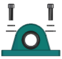
To create smart explode lines:
- Open an assembly that contains an exploded view.
- On the ConfigurationManager
 tab, expand the active configuration.
- Right-click the ExplView
 feature and click
Smart Explode Lines
feature and click
Smart Explode Lines
 .
.
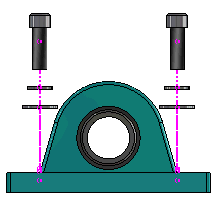
- In the Smart Explode Lines PropertyManager, click
 .
.The exploded view contains the smart explode
lines.

Dissolving Smart Explode Lines
To change a line created by using the Smart Explode
Lines option, you must dissolve the smart explode line.
To dissolve a smart explode line:
- On the ConfigurationManager tab, expand the active configuration.
- Expand the ExplView
feature.
- Right-click the 3DExplode
 sketch and click
Edit Sketch.
sketch and click
Edit Sketch. When you edit the
sketch, the smart explode lines appear in the color selected for the
Highlight setting. To change this color, click . In the Color scheme settings section,
select Highlight.
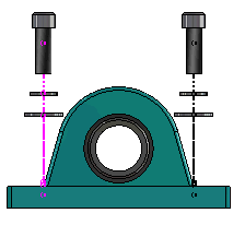
- Right-click the smart explode line and click Dissolve
Entities
 .
. In the
following image, the route line on the right side is dissolved. The route
line on the left side remains a smart explode line.
To dissolve all smart explode lines:
- On the ConfigurationManager tab, expand the active configuration.
- Expand the ExplView
feature.
- Right-click the 3DExplode
sketch and click
Dissolve Smart Explode Lines
.
To edit
the lines, you must edit the sketch.