Use a solid mesh to analyze thicker parts and view results throughout the part thickness. A solid mesh provides better accuracy for models with more complex or detailed geometry but requires longer computational time for the solution.
To create a solid mesh, do one of the following:
- Click Solid Mesh (Automatic) or Solid Mesh (Manual)(SOLIDWORKS Plastics CommandManager).
- In the PlasticsManager
 , double-click Solid and click Auto or Manual.
Automatic Mesh
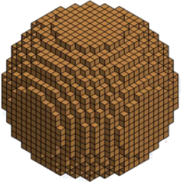
When you select the Automatic method, the software selects the default size of the solid element based on the cavity size and thickness. The Automatic method produces a coarser robust mesh compared to the default mesh size of the Manual method. The automatic mesh generation is based on the Marching Voxel method composed of hexahedra elements.
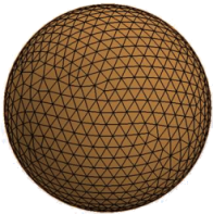
For a better visualization, and to avoid showing a stair-stepped mesh along curved surfaces, the mesh is shown with tetrahedra elements.
 |
 |
| Mesh view of a sphere cavity meshed with the Automatic method. Mesh is rendered with tetrahedral mesh to capture more accurately the geometry resolution. |
Mesh view of the actual meshed geometry with the underlying hexahedral mesh (visible when you define an injection location). |
The program supports automatic meshing for a single cavity only.
Manual Mesh
When you select the Manual method, you create the solid mesh in a step-by-step process. The software transforms the triangular surface mesh to fill the volume of the cavity. A solid mesh can be composed of tetrahedra, hexahedra, or a combination of elements (hybrid mesh with prisms and tetrahedra).
 |
 |
 |
| Tetrahedron (tetra) |
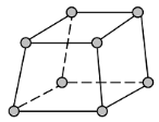
Hexahedron (brick) |
Triangular prism (wedge) |
Select Manual mesh to:
- Set the mesh size and refine the mesh in selected regions. By creating a more refined mesh with smaller cells, the simulation can predict more detailed material and flow behavior at the expense of longer simulation times.
- Improve the results accuracy for models with complex geometry or detailed features.
- Use mesh editing tools to improve the mesh quality.
- Predict the position of weld lines after you run a FLOW Analysis.
When selecting the solid mesh type to mesh a part, consider the recommendations in the table.
| Mesh Type |
Geometry (Domain) Type |
|---|
| Tetrahedral |
Cooling system and mold |
| Hybrid |
Cavity, insert, and runner Captures the high gradients in temperature and velocity using boundary layer elements.
|
| Hexahedral Voxel |
Cavity Provides a robust mesh for complex geometry, but it is less accurate in capturing the geometry of detailed features or high-curvature surfaces.
|
| Hexahedral marching |
Cavity Captures the geometry of detailed features more accurately than the Voxel mesh.
|
| Hexahedral non-orthogonal |
Cavity Produces the most accurate analysis when the mesh is sufficiently fine. The surface mesh should be of good quality (no holes, intersecting elements, or non-manifold elements), otherwise the mesh generation can fail.
|