The Channel Design PropertyManager sets the design parameters for creating cooling channels to regulate the temperature of the mold cavity or runner layouts to control the flow of the melted plastic.
To open the Channel Design PropertyManager:
- In the Solid PropertyManager, select .
Cooling channels are passageways located within the body of a mold
through which a cooling medium, typically water, steam or oil,
circulates. Cooling channels regulate the temperature of the mold. You use lines of an existing sketch to specify the layout of the cooling channel.
By creating a sketch to define the cooling channel layout, you get more accurate COOL analysis results (such as part cooling time, and part and mold temperatures at end of cooling)
You can select one of the available standard cross-sections for the runner type, or select the Runner Wizard to assist you with defining the design parameters of the runner components for a single or multi-cavity mold layout.
Type
| Cooling Channel |
|
General
|
This is the most common design of a cooling channel. It is
generated by entering the diameters at the two end nodes connected
by line elements.
 |
| Schematic representation of a cooling channel layout. 1: Input Node, 2: Output Node
|
|
|
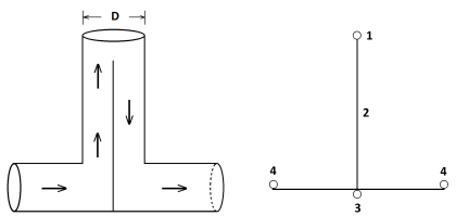
Baffle
|
This type of cooling channel is generated by entering one
diameter for the two end nodes, where the bottom node is connected
to the node of a line element and the top node is isolated.
 |
| Schematic representation of a Baffle cooling channel. 1: Top Node, 2: Baffle, 3: Bottom Node, and 4: Channel Element
|
|
|
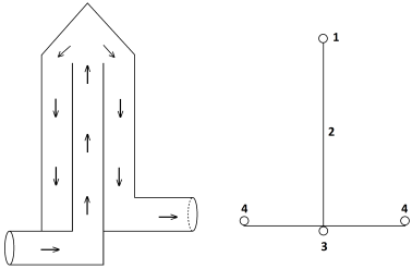
Bubbler
|
This type of cooling channel is generated by entering two diameters (tube cross-section) for the two end nodes. The bottom node connects to the line element and the top node is isolated.
 |
| Schematic representation of a Bubbler cooling channel. 1: Top Node, 2: Bubbler, 3: Bottom Node, and 4: Channel Element
|
|
|
|
Runner
|
|
| Runner Wizard |
Opens the Channel Design Wizard which automates the process of creating common flow control devices and components such as sprues, runners and gates. |
|
Flip Dimension
|
Reverses the dimensions for the selected runner. |
Parameters
|
Design Variables
|
Sets the dimensions for the runner design variables. |
|
Rotate Angle
|
Sets the angle of rotation for the cooling channel or runner. |
|
Element Count
|
Sets the number of elements for meshing the cooling channel or runner components. |
|
Apply
|
Applies the current design parameters. |
|
Delete
|
Removes the current design parameters. |
Injection locations are located at the top of the sprue component.