Use the G-Code Generator to create machine-readable G-code from your 2D drawing for CNC machines.
To
enable the
G-Code Generator:
- Click .
- Right-click the top of the DraftSight Window and click
G-Code Generator.
Top toolbar
| |
G-code type
|
Shows the type of G-code that will be generated. Available types are:
- 2D Toolpath
Defines how the engraving tool moves.
- Drill cycle
Defines how holes are drilled in the work piece.
|
 |
Generate
|
Creates the initial G-code, which you can modify using the G-Code Generator panel. Generating creates a preview of the toolpath for the selected entities.
If you have entities selected in the graphics area, they are used to generate the initial file.
If nothing is selected, you are prompted to select one or more entities.
|
 |
Select file
|
Opens the Preview File dialog box, to let you locate and select an existing G-code file to open. You can open only .txt or .ngc files in the GCode Generator.
You can use Select File to open a G-code file in the G-Code Generator without opening the drawing that was used to create it
|
 |
Save
|
Opens the
Save File dialog box, where you can save the current G-code file as a .txt or .ngc file so it can be transferred to a CNC machine. |
 |
Help |
Opens this help topic. |
G-Code parameters - 2D Toolpath
| Comments |
Contains comments about the file. |
|
Preamble
|
Displays the set up code at the beginning of the G-Code
file. DraftSight provides a default Preamble,
which includes settings required by the CNC machine to start the
spindle and set the RPM.
You can create
your own preamble in a text editor and copy and paste it into
the Preamble field.
Show
line numbers displays line numbers at the
beginning of each line for the entire file.
|
|
Postscript
|
Displays the code inserted at the end of the G-Code file to reset the machine. DraftSight provides a default Postscript, which includes settings to shut off the spindle and retract it to a safe height.
|
| Units |
Sets units of measurement to
millimeters or
inches. Relative
sets coordinates relative to the current position of the machine.
Absolute sets origin coordinates to
0.0. |
|
Z Safe Height
|
Shows the Z height during non-cutting moves. |
|
Z Retraction
|
Shows the Z height when cutting is over. |
|
FeedRate Z
|
Shows the feed rate along the Z axis when plunging into the work piece. |
|
FeedRate XY
|
Shows the feed rate along the XY axes during cutting along the XY axes. |
|
Depth of Cut
|
Shows how much the Z axis moves into the work piece. |
|
Peck Depth
|
Shows the depth of each peck. |
G-Code parameters - Drill Cycle
Drill cycle options can be used for points and circles only. Other entities that are selected are ignored.
|
Preamble
|
Displays the set up code at the beginning of the G-Code file. DraftSight provides a default Preamble, which includes settings required by the CNC machine to start the spindle and set the RPM.
You can create your own preamble in a text editor and copy and paste it into the Preamble field.
|
|
Postscript
|
Displays the code inserted at the end of the G-Code file to reset the machine. DraftSight provides a default Postscript, which includes settings to shut off the spindle and retract it to a safe height.
|
|
Drill cycle type
|
Shows the selected drill cycle type. Options are:
|
G81
|
Drill cycle
|
|
G82
|
Drill cycle with dwell
|
|
G83
|
Peck drill cycle
|
The drill cycle type you select determines the rest of the options that are available.
|
|
Drill Feedrate
|
All drill types Shows the feed rate at which drilling will occur.
|
|
Depth
|
All drill types Shows the final depth of the cut.
|
|
Retract height
|
All drill types Shows the height to which the tool moves after drilling a hole, before it moves to the next hole.
|
|
Dwell
|
G82 (Drill cycle with dwell) and G83 (Peck drill cycle) only Shows the length of time the tool is motionless between drill operations.
|
|
Peck Depth
|
G83 (Peck drill cycle) only Shows the depth of each peck.
|
Preview and Preview Controls
A preview of the toolpath or drill cycle you select appears in the
window of the G-Code Generator panel.
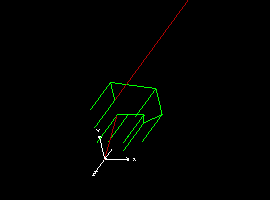
The preview shows the X, Y, and Z axes, the location of selected
entities, the tool path for cutting,
and
the drill depth
for drill
cycles.
Controls
in
the preview let you view a simulation of the tool path or drill
sequence.
Additional controls help you move the image in the preview
window.