The software provides a set of predefined drawing Frames and Title Blocks
for each engineering standard. Also, you can create custom Frames and Title Blocks according
to your requirements.
To use custom Frame and Title Blocks in other drawings, you must create and
save them in DWG format and store them in specific folders,
similarly
to the standard ones.
You can change the default location for Frame and Title Block files in the
Options dialog box. You can add as many locations as
required.
-
To create a custom
Frame:
-
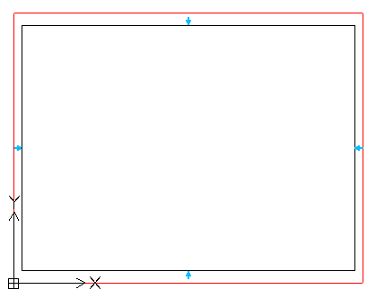
In a blank new drawing, draw the following elements that form the Frame
using standard commands and entities:
- Outer rectangle: Create a rectangle using the
(0,0) point as
a
lower-left
corner
- Inner rectangle
- Centering marks: Draw centering marks on each
side of the inner rectangle using geometric entities.

-
Save the file.
For clarity, you can use the following naming rule:
Language_Standard_(Size). For example, EN_ANSI Inch_A (8.5 x
11 Inches
).
-
To identify the Frame extent, add a SimpleNote to the following corners
of the rectangle:
- Lower-left:
FRAME_LL
- Upper-right:
FRAME_UR
- Lower-right:
FRAME_LR
The text grip point should exactly match the rectangle grip
point.
-
Place the drawing in the location specified in the Options dialog
box.
-
To create a custom Title Block:
-
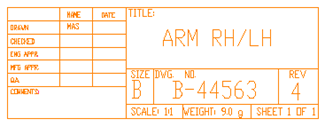
In a blank new drawing, draw the following elements that form the Title
Block using standard commands:
- The boundary: Create a rectangle using (0,0) point as
a lower-right
corner.
- Partition lines: Draw lines as
required
for the Title Block layout.
- Header: Draw the lines defining the Title Block header.

-
Save the file.
For clarity, you can use the following naming rule:
Language_Standard_TitleBlock. For example, EN_ANSI
Inch_TitleBlock.
-
Define the BlockAttributes and place them within the
Title Block as
required.
-
Place the drawing in the location specified in the Options dialog
box.