| Using a Reference Plane |
A reference plane (or a planar face) defines two
directions in its plane and a third direction, which is normal to the
plane. The two directions in the plane are referred to as Plane dir 1 and Plane dir 2. They are parallel to the
boundaries of the plane, and assigned internally by the program. These
directions cannot be modified. When applying
restraints and loads, select Show
preview to identify Plane Dir 1 and Plane Dir 2. The
arrows of the load or restraint symbols point to the positive Plane
Dir 1, Plane Dir 2, and normal to the plane directions.
You can identify the normal direction by the
right-hand rule: thumb finger points to positive Plane Dir 1, index
finger points to positive Plane Dir 2, middle finger points to the
positive normal direction.
For material
properties directions, Dir 1 aligns with the X-dir, Dir 2 with the
Y-dir, and normal to the plane with the Z-dir.
|
| Using Front,
Right, and Top plane
as reference geometry. |
The table lists the direction
orientation with respect to the global coordinate system, when you
select one of the Front,
Right, or Top plane as
a reference geometry.
| Front
Plane |
Dir 1
aligns with the global X direction. Dir 2
aligns with the global Y direction.
Normal to the plane aligns with
the global Z direction.
|
| Right
Plane |
Dir 1 aligns with the
global Z direction. Dir 2 aligns with the
global Y direction.
Normal
to the plane aligns with the global X
direction.
|
| Top
Plane |
Dir 1 aligns with the
global X direction. Dir 2 aligns with the
global Z direction.
Normal
to the plane aligns with the global Y
direction.
|
|
| Coordinate Systems |
A coordinate system defines 3
directions, X, Y, and Z. The default coordinate system used by the
software, called the global coordinate system, is based on Plane1
(Front Plane). The origin of the global
coordinate system is located at the origin of the part or assembly.
Plane1 is the top reference plane that appears in the FeatureManager
design tree. The reference triad shows the global X-, Y-, and
Z-directions. All other coordinate systems are referred to as local
coordinate systems. You can define a local coordinate
system with .
|
| Using a Reference Axis |
A reference axis defines a radial
direction, a circumferential direction, and an axial direction. When
applying restraints and loads, select the Show preview check box in the PropertyManager to
identify the positive directions. Use negative values for the opposite
direction.When specifying a circumferential
translation, you specify an angle (Θ) in radians. This sets the
translation in the circumferential direction (v) to: v = r.Θ, where
r is the radius of the node at which the restraint is applied
relative to the reference axis.
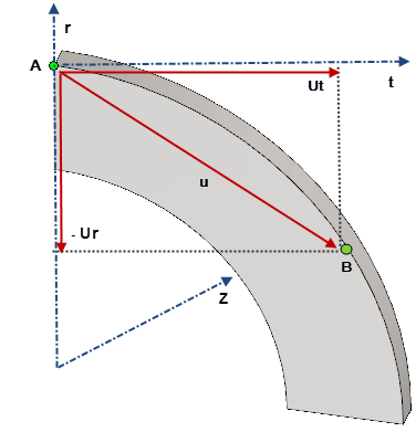
When viewing deformation results with respect to a reference axis, the
displacement vectors are reported as Ur,
Ut, and UZ, where r represents the
radial direction, t the tangential direction, and z the
axial direction. This r- t -z system is with respect to each
node’s original configuration.
Taking a quarter ring as an example, suppose that a node A is displaced
from its original position to point B and the displacement
vector at the end of a nonlinear solution is defined by u.
The program reports for the radial displacement
Ur a negative value in node A’s original
radial direction and for the tangential direction a positive
value Ut in node A’s original tangential
direction. Note that Ur does not necessarily
indicate an expansion (or contraction) of the ring and
Ut does not indicate a rotation of the ring
as well.
 |
| Using a Cylindrical Face |
This is similar to using a reference
axis. The axis of the cylindrical face is used as the reference axis.
|
| Using a Straight Edge |
A straight edge defines one direction.
When applying restraints and loads, select the Show preview check box in the
PropertyManager to identify the positive direction. |