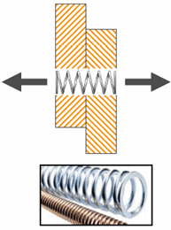
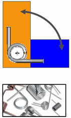
A
pin's axial stiffness defines the relative axial movement between the cylindrical faces (or
circular edges) connected to it. A pin's rotational stiffness defines the relative rotational
movement between the connected cylindrical faces (or circular edges). All
applicable studies model the spring used for a pin connector as linear elastic.
You can estimate the axial and rotational stiffness values based on the actual pin rod
geometry.
| Axial stiffness |
Rotational stiffness |
 |
 |
| You can use the linear stiffness of a rod with
constant diameter in tension. K = AE/L
A is the
cross sectional area of the spring
E is the elastic modulus of
the spring
L is the free length of the spring without any
deflection
|
You can use the linear stiffness of rod with
constant diameter in torsion. K = JG/L
J is
the polar moment of inertia = 2I
I is the moment of inertia =
(Πr4)/4
r is the radius of the coil
G is the modulus of rigidity = E/(2(1+ν))
E
is the elastic modulus of the spring
ν is the Poisson's
ratio
L is the free length of the spring without any
deflection
|
For a pin connecting more than two cylindrical faces or edges, the software redistributes the
axial and rotational stiffnesses based on each pin segment's geometric properties (such as
sectional area, polar moment of inertia, and length). A pin segment connects two consecutive
cylindrical faces and has two end joints.