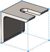
You can create a bounding box for a multibody, single body, or sheet
metal part. You can also create a bounding box for any cut list item in a cut list,
independent of the type of solid or sheet metal bodies in the item.

The bounding box is represented by a 3D sketch and is based, by default,
on the X-Y plane. Taking into consideration the bounding box's orientation, the bounding
box is the smallest box in which the body fits.
Benefits of bounding boxes:
- For parts, bounding box
dimensions are available as properties in the Configuration Specific tab of the Summary Information dialog
box. For cut lists,
the overall dimensions of the bounding box appear in the Cut-List Properties dialog box. You can use these
dimensions in a bill of materials or other annotations.
- With a bounding box, you can determine the length, width, and height of the
stock required for the body. This helps you to know how much space is required
for packaging the product.
- With weldments, you no longer have to find the stock size for
plates manually.
Bounding Box Orientation
The orientation of a bounding box is based on one of the
following:
- The X-Y plane (default)
- A preselected plane or planar face
Exceptions to these orientations are for weldment gussets and end
caps:
- For gussets, the orientation plane for the bounding box is
parallel to the gusset faces.
- For end caps, the orientation plane for the bounding box is
parallel to the planar faces that they cap.
- For a linear structural member, the orientation plane for the
bounding box is perpendicular to the sketch line defining the member.