You can access the features of a multibody sheet metal part in the main FeatureManager design tree or in a cut list added to the top of the tree. Features are tracked in both.
The features you add to create the multibody part are represented separately in the cut list and as new features in the main FeatureManager design tree.
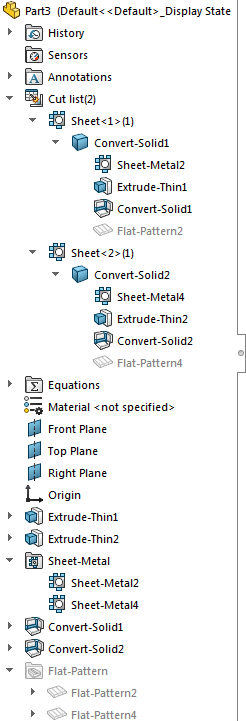
For example, when you create a multibody part by using Convert to Sheet Metal to add sheet metal bodies, the Convert-Solid features are added to the FeatureManager design tree as they are created and representations of the bodies are added to the cut list. In parts created with SOLIDWORKS 2013 and newer, there are two separate parent folders (Sheet-Metal  and Flat-Pattern
  ) that contain the sheet metal bodies and their associated flat patterns.
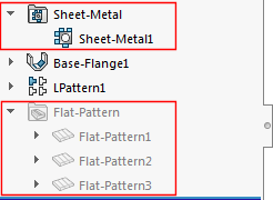
If you create a new sheet metal body from an existing sheet metal body, only one
Sheet-Metal feature appears in the parent sheet metal folder in the FeatureManager design tree. For example, if you pattern a sheet metal body so there are three sheet metal bodies instead of one, only one sheet metal feature node corresponding to the three resulting bodies controls the sheet metal parameters of the bodies.
If you attach two existing bodies to create one sheet metal body, two Sheet-Metal  features appear in the parent sheet metal folder in the FeatureManager design tree. Even though there is only one body, the second body retains its own sheet metal parameters.
The sheet metal feature that corresponds to the first body controls the first body geometry as well as any new feature geometry added to the combined body.
The sheet metal feature that corresponds to the second body is indented under the sheet metal feature that corresponds to the first body.
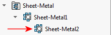
It controls only the second body geometry (thickness and bend radius).
In the cut list:
- Each body has its own sheet metal definition.
The body is named for the last feature added to it.
- Expand a body's representation to access and edit features.
Although you cannot expand a feature to see its sketch, you can edit the sketch by right-clicking the feature and clicking Edit Sketch  .
.
- You can use the right-click menu to give each body its own material definition and isolate or flatten the selected body.
- A flat pattern specific to the body appears at the bottom of the feature list.
In the main FeatureManager design tree:
- All of the features that were used to create the multibody part are listed in the order in which they were created.
- You can edit features from the main FeatureManager design tree or from the cut list.
- The FeatureManager design tree ends with a separate flat pattern for each body in the multibody part.
- If you use Insert Part to add bodies to a part, in addition to representations of the bodies being added to the cut list, a node is added for each new body in the main FeatureManager design tree.