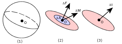
The internal forces in a body will vary from one point to the other. Across any small internal plane area, loads are exerted by the part of the body on one side of the area upon the part on the other side. Stress denotes the intensity of these internal forces (force per unit area).
Stress
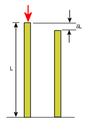
In a continuous body, you can calculate the stress at a point as follows:
- Imagine an arbitrary plane that cuts through the body at that point,
- Consider an infinitesimally small area ΔA around that point on the plane,
- Suppose that the magnitude of force transmitted across ΔA in a certain direction is ΔF,
- The stress in that direction is then given by ΔF/ΔA as ΔA approaches 0.
The above defines a stress or traction vector at a point. Traction vector does not uniquely define state of stress at a point. It varies depending on the arbitrary plane chosen. A stress tensor, for example, true stress tensor defined as σ = n.T (matrix multiplication), where n is the normal vector associated with the plane and T is the stress or traction vector, defines stress uniquely.

Figure (1): A plane passing through point O and dividing the body into two parts.
Figure (2): Resultant force and moment vectors on a region of area ΔA about point O in the plane.
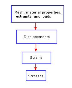
Figure (3): Limiting stress vector at point O in the plane.
Strain
Strain is the ratio of change in length δL to the original length L. Strain is a dimensionless quantity.

Strain = δL/L
Sequence of Calculations
Given a meshed model with a set of displacement restraints and loads, the linear static analysis program proceeds as follows:
- The program constructs and solves a system of linear simultaneous finite element equilibrium equations to calculate displacement components at each node.
- The program then uses the displacement results to calculate the strain components.
- The program uses the strain results and the stress-strain relationships to calculate the stresses.

Stress Calculations
Stress results are first calculated at special points, called Gaussian points or Quadrature points, located inside each element. These points are selected to give optimal numerical results. The program calculates stresses at the nodes of each element by extrapolating the results available at the Gaussian points.
After a successful run, nodal stress results at each node of every element are available in the database. Nodes common to two or more elements have multiple results. In general, these results are not identical because the finite element method is an approximate method. For example, if a node is common to three elements, there can be three slightly different values for every stress component at that node.
When viewing stress results, you can ask for element stresses or nodal stresses. To calculate element stresses, the program averages the corresponding nodal stresses for each element. To calculate nodal stresses, the program averages the corresponding results from all elements sharing that node.