The orthotropic material directions throughout a component are defined based on the selected reference geometry selected.
If a part is manufactured such that you cannot define a common reference geometry for the whole component, then you should model it as different parts to define orthotropic directions properly.
The reference geometry is selected in the Material dialog box when you select Linear Elastic Orthotropic for Model Type.
For example, consider the part shown in the figure:
You need to model this part as two parts: the cylinder and the planar sheet. You can then use a plane as the reference geometry for defining the orthotropic material directions for the planar sheet and the axis of the cylinder as the reference geometry for the cylinder.
 |
 |
| The radial (X), tangential (Y), and axial directions (Z) for an orthotropic material when an axis is used as a reference geometry.
|
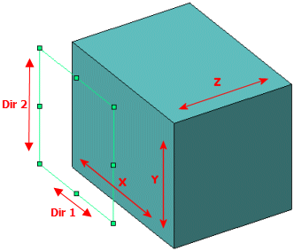
When a plane (or a planar face) is used as a reference
geometry, Dir 1 of the plane aligns with the
X material direction, Dir 2 of the plane with
the Y material direction, and the normal to the plane with the Z
material direction. The table lists the direction
orientation with respect to the global coordinate system, when
you select one of the Front,
Right, or Top
plane as a reference geometry.
| Front |
Dir 1
aligns with the global X direction.
Dir 2
aligns with the global Y direction.
Normal to the plane aligns with
the global Z direction.
|
| Right |
Dir 1 aligns with the global Z direction.
Dir 2 aligns with the global Y direction.
Normal to the plane aligns with
the global X direction.
|
| Top |
Dir 1 aligns with the global X direction.
Dir 2 aligns with the global Z direction.
Normal to the plane aligns with
the global Y direction.
|
To identify Dir 1 and
Dir 2 of the reference plane, select
the plane as reference geometry when applying restraints or
loads and select Show
Preview.
|