| N/A
|
- Name
Specifies the actor name. This name appears in the Collaboration or Assembly tree and is the default tooltip text.
|


|
- Tooltip
Specifies the tooltip text that appears when you hover over the actor. The default is the actor name, but you can select a different property or meta-property, or type a text string. To type text, which itself can contain properties, select
String and use the
Tooltip string property.
Note:
By default, labels attached to an actor display the actor's tooltip text. To change this behavior, modify the label's
Text property.
|


|
- Tooltip string
(Available when
Tooltip is
String.) Specifies the tooltip text. Type your text, optionally with
property keywords. For geometry actors, click
 to display the
Text pane, where you can type multiple lines of text and more easily embed properties. to display the
Text pane, where you can type multiple lines of text and more easily embed properties.
See Text pane for details on property keywords and the Text pane.
|


|
- Color
Specifies the actor color.
|

|
- Opacity
Specifies the opacity, from 0 (transparent) to 255 (solid).
|


|
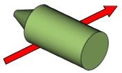
- Stay on top
Makes the collaborative actor visible even when a geometry actor covers it.
 |
 |
| Disabled
|
Enabled
|
|


|
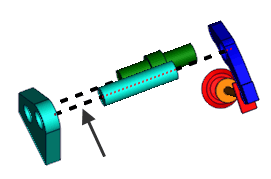
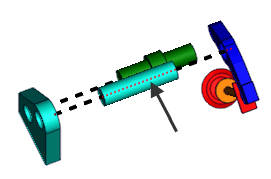
- Hidden style
-
(Available when
Stay on top is cleared.) Enables
Back line properties. A back line passes under
actors that are on top. You can define different styles for front and back
lines.
|
|
| Front Line
|
Back Line
|
|

|
- Smooth
-
Creates curved polyline segments (cubic Hermite
splines).

|

|
| Disabled
|
Enabled
|
|

|
- Close
-
Connects the first and last nodes to create a closed
polyline space.

|

|
| Disabled
|
Enabled
|
|

|
- Line width
- Specifies redline thickness, in millimeters.
|

|
- Radius
Specifies the radius, in millimeters.
|

|
- Show axis vertices
-
Displays the axis of the circular arrow, which helps indicate its
orientation.

|

|
| Disabled
|
Enabled
|
|

|
| Arrow shape
|
- Fixed Size Arrow
-
Specifies that the arrow size must remain fixed, no
matter what the zoom factor is. This ensure that the arrow remains visible at
all times.
|

|
- Fixed Length
-
Specifies the required length of the arrow, when
Fixed Size Arrow is selected. The
length is defined according to paper dimensions.
|

|
- Extremity
-
Specifies where to place arrowheads.
The
Head shape,
Head width, and
Head length properties define arrowhead shape and
size.
Tip:
To easily change arrow shape and size properties, drag
anchors in the viewport.

|


|
- Head Shape
-
Specifies where the arrowhead meets the shaft specified
as a ratio of head length (-1 to 1, with 0 being perpendicular).
Note:
To avoid deformed arrows, the value
range (-1 to 1) might be reduced when dragging the head-shape anchor
 in the viewport. in the viewport.
|


|
- Head width
-
Specifies the arrowhead width, in document length units,
as measured from the shaft centerline.

|

|
| 20
|
60
|
Tip:
To change head and shaft widths
simultaneously, drag the head-width anchor
 in the viewport. To change just head width,
press
Shift while dragging the anchor. in the viewport. To change just head width,
press
Shift while dragging the anchor.
|


|
- Head length
-
Specifies the arrowhead length, in document length
units. Changing arrowhead length does not change the overall arrow length
(Length).
|


|
- Width
-
Specifies the arrow shaft width, in document length units.
|


|
- Length
-
Specifies the arrow length, in document length units.
Note:
This property is disabled for linear arrows, when
Fixed Size Arrow is enabled.
Tip:
When changing the length of a linear arrow by dragging an
 anchor in the viewport, an axis line appears to help you retain
the arrow orientation. You can also press
Alt while dragging to lock the orientation. anchor in the viewport, an axis line appears to help you retain
the arrow orientation. You can also press
Alt while dragging to lock the orientation.

|


|
- Flat
-
Specifies the flat representation of a circular arrow.

|

|
| Disabled
|
Enabled
|
|

|
- Radius
Specifies the radius, in millimeters.
|

|
- Step
-
Specifies the number of curve segments.
|

|
- Angle
-
Specifies the number of degrees (0 to 360) of a circular arrow.

|

|
| 90
|
270
|
Tip:
You can also change
Angle and
Radius by dragging the arrow in the viewport. A
dashed line shows the original radius. The arrow snaps to this line when nearby
so you can easily change the rotation angle without changing the radius.
|

|
| Background
|
- Color
Specifies the background color.
|


|
- Opacity
Specifies the opacity, from 0 (transparent) to 255 (solid).
|


|
- Thickness
Specifies the thickness of the circle background as a percentage.
|

|
- Type
Specifies the background style.
|

|
- Gradient
Specifies the gradient effect.
|


|
| Fill
|
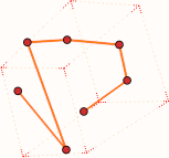
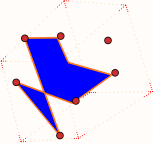
- Fill
-
Applies a fill color to the polyline interior. Composer
flattens the polyline to a 2D plane defined by the first three polyline nodes.
Nodes not on the plane are projected onto the plane to define the polyline
shape.
|
|
| Disabled
|
Enabled
Color = blue
Opacity = 255
|
Note:
Z-fighting can occur for filled
polylines on 3D geometry when
Stay on top is disabled. To
prevent Z-fighting, translate the polyline so it is offset from the 3D surface,
or enable
Stay on top.
|

|
- Color
- Specifies the fill color.
|

|
- Opacity
- Specifies the fill opacity.
|

|
| Border
|
- Show
Displays the border.
|


|
- Width
Specifies the border line width, in millimeters.
|


|
- Opacity
Specifies the border opacity (between 0 and 255).
|


|
- Color
Specifies the border color.
|


|
- Type
-
Specifies the border type.

|


|
| Inlaid Text
|
- Show inlaid text
- Displays text inside a linear arrow.
|

|
- Color
- Specifies the
- color of the inlaid text.
|

|
- Type
- Specifies the type of text to display inside the arrow:
- Length displays the length of
the arrow (in model coordinates). Not available for fixed-size arrows.
- Custom displays text you
specify.
|

|
- Text
- (Available when
Custom is selected.) Specifies the
text to display inside the arrow.
|

|
| Back Border
|
- Show
- (Available when
Stay on top is cleared and when
Hidden Style is selected.) Displays
the back border.
|

|
- Width
- Specifies the width of the back border line, in
millimeters.
|

|
- Opacity
- Specifies the back border opacity (between 0 and 255).
|

|
- Color
- Specifies the back border color.
|

|
- Type
- Specifies the back border type.
|

|
| Line
|
- Width
Specifies the line width, in millimeters.
|

|
- Opacity
Specifies the actor opacity (between 0 and 255).
|

|
- Color
Specifies the line color.
|

|
- Type
Specifies the line style.

|

|
| Front line/Back line (
Back line available when
Hidden style is selected)
|
- Width
Specifies the line width, in millimeters.
|

|
- Opacity
Specifies the actor opacity (between 0 and 255).
|

|
- Color
Specifies the line color.
|

|
- Type
Specifies the line style.

|
Selects a predefined style.
|
| User defined |
Defines a custom dashed-line style (see the
Dash pattern property).
|
| Advanced |
Defines a custom line style using symbols and custom spacing (see the
Symbol #
n,
Symbol size, and
Space between symbols properties).
|
|

|
- Dash pattern
(Available when
Type is
User defined.) Defines the line as a repeating series of dashes and spaces of the specified lengths, in millimeters. For example,
2.0 4.0 8.0 8.0 defines a 2 mm dash followed by a 4 mm space followed by an 8 mm dash followed by an 8 mm space, and then repeat.

|
 |
| 2.0 2.0
|
2.0 4.0 8.0 8.0
|
|

|
|
Symbol #1, Symbol #2, Symbol #3, Symbol #4
- Style
-
(Available when
Type is
Advanced.) Defines a custom line style consisting
of up to 4 different symbols.
|
|
None
|

|
Bold arrow
|

|
Medium arrow
|

|
Thin arrow
|

|
Rhombus
|

|
Round
|

|
Cross
|

|
Star
|

|
Plus
|

|
Square
|

|
Minus
|

|
Half Sinus up
|

|
Half Sinus down
|

|
Small round
|
|

|
- Symbol size
(Available when
Type is
Advanced.) Specifies the size of each symbol.
|

|
- Space between symbols
-
(Available when
Type is
Advanced.) Specifies the space between symbols as
a multiplier of
Symbol size.

|

|

|
| -0.5 (overlapping)
|
0 (touching)
|
1 (one symbol width)
|
|

|
| Extremity
|
- Start
-
Specifies the extremity symbol for the line start point.

|
None
|

|
Bold arrow
|

|
Medium arrow
|

|
Thin arrow
|

|
Rhombus
|

|
Round
|

|
Cross
|

|
Arrow
|
|

|
- End
-
Specifies the extremity symbol for the line end point.

|
None
|

|
Bold arrow
|

|
Medium arrow
|

|
Thin arrow
|

|
Rhombus
|

|
Round
|

|
Cross
|

|
Arrow
|
|

|
- Size
Specifies the size of the extremity symbol (between 0.5 and 100).
|

|