The Solid analysis procedure requires a solid
mesh. A solid mesh is appropriate for thick parts and models with complex
geometry.
You can create three types of solid meshes:
- Tetrahedral Hybrid
- Hexahedral
- Automatic
Tetrahedral Hybrid
The tetrahedral hybrid mesh type uses a triangular surface mesh as a basis
for creating tetrahedral volume elements, generally combined with boundary layers.
Boundary layers are layers of prismatic elements at the surface of the body. When
you span gaps that are small relative to the local surface mesh size, a prismatic
element is better able to maintain a high-quality, less-distorted shape than a
tetrahedral element. In general, for thin gaps you need 5 boundary layers of
prismatic elements to get accurate and robust flow solutions. By default, the
software creates 2 boundary layers.
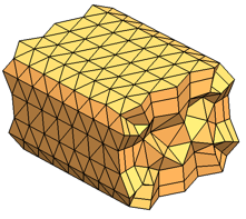 |
| Example: Hybrid tetrahedral mesh |
Hexahedral
The hexahedral mesh type uses nonorthogonal hexahedral elements to fill the
volume of a domain. In regions where the software cannot create hexahedral elements
of sufficiently high quality, the software instead creates tetrahedral elements.
Hexahedral elements, when aligned with the part cavity (and hence the melt
flow) can potentially deliver more accurate and efficient solutions. However, the
hexahedral mesh type might not be suited to all shapes. The software first creates a
triangular surface mesh as a preprocessing step, and then bases the hexahedral
meshing on this surface mesh rather than the part geometry. This extra step
introduces a potential source of error in terms of approximation to the original
geometry.
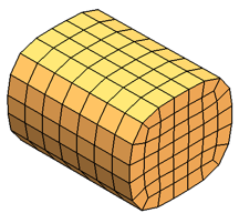
|
| Example: Hexahedral mesh |
Automatic
The Automatic mesh type is the
fastest way to create a mesh with minimum user intervention. The software assigns a
mesh size based on the part dimensions, and applies a curvature-based refinement to
capture small features. Where possible, the software creates a tetrahedral hybrid
mesh. If meshing fails because of geometry issues, such as non-manifold edges or
gaps between surfaces in the model, the software creates a Cartesian voxel mesh.
Use the Automatic mesh option for
rapid analysis. Be cautious because the voxel mesh cannot always accurately
represent the geometry. For accurate analysis, use the Tetrahedral Hybrid or Hexahedral mesh types.
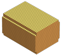 |
| Example: Voxel mesh. In this case, the software
failed to create a hybrid tetrahedral mesh. |