Harmonic analysis evaluates peak steady state response of a system to harmonic loads.
At each solution step, all applied loads and base excitations have the same frequency. The magnitudes are defined by the associated frequency curves.
Assume a harmonic nodal force vector {P} defined as:
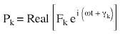 (Equation 1) or
 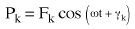 (Equation 2),
where:
Pk is the magnitude of the force in the direction of the kth degree of freedom
ω is the exciting frequency, and
γk is the phase angle of the force.
For linear systems, the system's equations of motion are de-coupled into n modal equations:
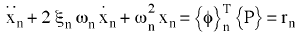 (Equation 3).
Substituting the force vector {P} into (Equation 3) results in:
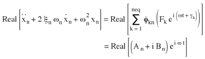 (Equation 4), where
 (Equation 5)
The steady state solution to (Equation 4) is:
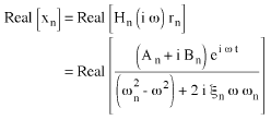 (Equation 6).
The real part of (Equation 6) is:
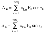
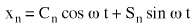 (Equation 7) where
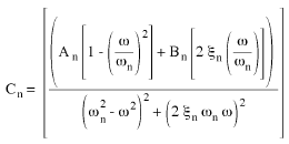 (Equation 8) and
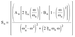 (Equation 9).
The displacement vector u is given by:
 (Equation 10) or
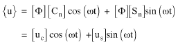 (Equation 11)
The magnitude of the displacement uk and the corresponding phase angle θkfor the kth degree of freedom are:
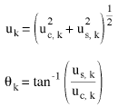 (Equation 12)
The velocity and acceleration responses are derived from the derivatives of (Equation 11). Their amplitudes are:
 (Equation 13)
The velocities and accelerations phase angles are 90º and 180º out of phase with respect to the displacement phase angles.