You can use spring connections between these types of geometric entities.
-
Concentric cylindrical faces of shell and solid
A cylinder with surfaces at the ends and solid along the entire length
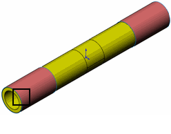
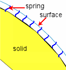
Springs defined in the common areas are obtained by projection. You define spring stiffness and preload forces per unit areas.
- Parallel circular edges of shells (sheet metal bodies)
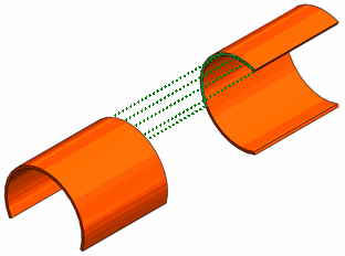
The springs inserted along the common circular arc lengths are obtained by projection.
The sheet metal bodies are meshed with two dimensional shell elements. After meshing, the face containing the thickness of the sheet metal becomes an edge. So, you define spring stiffness and preload forces per unit length.
- Circular edge of shell and a face on top of each other
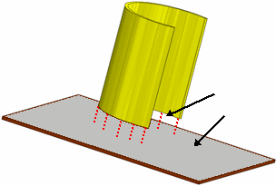
The springs are inserted between the circular edge and the projected circular arc on the solid face. You define spring stiffness and preload forces per unit length.
- Flat parallel edges of sheet metal on top of each other
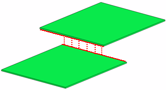
The springs inserted along common lengths of the edges are obtained by projection. You define spring stiffness and preload forces per unit length.
- Flat parallel faces
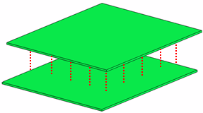
The springs inserted in the common area of the faces are obtained by projection. You define spring stiffness and preload forces per unit area.