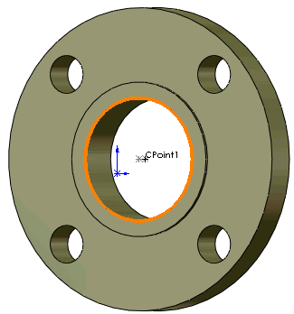
Use mate references for routing design wherever possible. Using mate references to place parts is more reliable and predictable than using SmartMates.
Always include mate references for routing components such as flanges. If you attempt to mate routing components after placing them in an assembly, you might introduce conflicts in the route sketch geometry.
Use the same name for all mate references applied to fittings with the same properties on a piece of equipment. A flange can be attached to any nozzle on a tank if the mate references on all nozzles, as well as the flange, have the same name. If one of the nozzles is threaded, give it a different name, and name the mate references of a threaded flange accordingly.
To ensure that routing parts mate correctly, define mate reference properties identically. For example, if the Primary Reference Entity on one part is defined as Face<1>, Coincident, Anti-Aligned, it should be defined identically on the second part. The same principle applies to secondary and tertiary entities.
Mate references are not used when you attach a component to the route sketch, for example, when you drag a tee onto the route to create a junction. In this case, SOLIDWORKS aligns the components so that the route point and connection points are coincident with the sketch lines.
Rules for Applying Mate References
Use the following general rules for placing mate references:
-
Add two mate references to a route fitting:
-
Add the first mate reference as a single edge mate to use with SmartMates when the mating component does not have a common mate reference.

SmartMates only use the first mate reference, so make sure that the single edge mate you create is listed first.
-
Add the other mate reference for mating the fitting to components with mate references of the same name and type.
Use specific mate types - coincident and concentric, rather than default mates.
- Add mate references to ports on equipment parts, adding one mate reference per port.
- If a piece of equipment has several ports, add mate references to all ports, or to none. SmartMates are used for part placement if there are no mate references on any of the ports.
- Add mate references to components used at the start and end of a route. Typically these are flanges or electrical connectors, but can also be valves or elbows.
- Add matching mate references to electrical connectors and their mating socket components.