Dimension Leaders PropertyManager

In the Dimension Leaders PropertyManager, you can specify the display of dimensions.

To open this PropertyManager:

Select one or more dimensions, then click Leaders in the Dimension PropertyManager.

If you select multiple dimensions, only the properties that apply to all the selected dimensions are available.

Witness/Leader Display

The type of arrows and leaders available depends on the type of dimension selected. See Example: Dimension Line Terminology.

Arrow Placement You can specify placement of arrows with respect to the dimension extension lines: Outside , Inside , Smart , Directed Leader .

Smart specifies that arrows automatically appear outside of extension lines if the space is too small to accommodate the dimension text and the arrowheads.

A Directed Leader can be oriented at any angle with respect to the surface of the feature and can be placed in an annotation plane parallel to the feature axis.

Circular arrowhead handles appear on dimension arrows when you select dimensions. The pointer changes to when it is over the arrowhead handles. When you click an arrowhead handle (either handle if there are two for the dimension), the arrows flip outside or inside.

Ordinate chain Select to chain ordinate dimensions. See Example: Dimension Scheme Types.
Style You can choose separate styles for each arrow when there are two arrows for a dimension. This feature supports the JIS dimensioning standard. Two lists appear in the Dimension PropertyManager only when separate styles are specified by the dimensioning standard.
Radius Specifies that the dimension on an arc or circle displays the radius.

Diameter Specifies that the dimension on an arc or circle displays the diameter.

Linear Specifies the display of a diameter dimension as a linear dimension (not radial).
Linear Radial
Foreshortened Specifies that the radius dimension line is foreshortened (broken). This is helpful when the center point of a radius is outside of the drawing or interferes with another drawing view. See Document Properties - Diameter Dimensions.
Use the dimension handles to reposition the center and bends.

If you move a diameter dimension into a view where it does not fit, it is foreshortened.

When you dimension to a foreshortened radius or diameter, the dimension also appears as a zigzag.
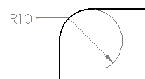
Solid Leader Specifies the display of a solid line across the circle for radial dimensions. Not available with ANSI standard.
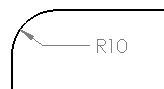
Open Leader  
One Arrow / Solid Leader  
One Arrow / Open Leader  
Two Arrows / Solid Leader  
Two Arrows / Open Leader  
Perpendicular to Axis (Available if you select Linear for a radial dimension)

Multi-jog Leader (Available for diameter, radius, and chamfer dimensions and hole callouts) See Setting Multiple Jogs in Dimension Leaders.

Parallel to Axis (Available if you select Linear for a radial dimension)

Arc extension line or opposite side
Controls the radial dimension leader:
  • Where possible, it is applied to an arc extension line.
  • If not possible, it is attached to the opposite side of the arc.
Arc extension line or opposite side selected Arc extension line or opposite side cleared
Use document second arrow Specifies that a diameter dimension (not displayed as linear) with outside arrows follows the document default setting for a second arrow.
To specify the document default setting, select Display second outside arrow in one of the following: To override the document default, clear Use document second arrow, then select Display second outside arrow to turn the arrow display on or off.
Second arrow ON Second arrow OFF
Use document bend length Uses the value for Bent leader length in Document Properties - Dimensions. When cleared, you can specify the dimension bent leader length. Enter a value in the box.
Extend bent leader to text If selected, this option specifies that shoulders of bent leaders for radius, diameter, chamfer, and hole callouts meet and align with the end of the text in the appropriate line of text.
  • Left- and right-sided leaders set to Top Justify center to the top line of text in the dimension.
  • Left- and right-sided leaders set to Bottom Justify center to the bottom line of text in the dimension.
If this option is cleared, the shoulders of bent leaders stop at the dimension text bounding box.

To set a default option, click Tools > Options > Document Properties > Dimensions. Under Bent leaders, select Extend to text.

Break Lines

Break Lines Select for the dimension and extension lines to break when crossing other dimension or extension lines in drawings.
You can choose for the extension lines to break only when crossing arrowheads. See Document Properties - Dimensions and select Break only around dimension arrows.
Selected
Cleared
When the dimension lines are broken, they break around lines that are nearby. If a dimension is moved significantly, it may not break around the new nearby dimensions. To update the display, unbreak the dimension lines and then break them again.
Use document gap Uses the value in Document Properties - Dimensions.
Gap Enter a value if you do not use the document default.
Break extension lines Breaks extension lines around dimension lines and other extension lines.

Break dimension line Breaks the dimension line around other dimension lines and other extension lines.

Custom Text Position

  Radial Dimension Text
Solid Leader, Aligned Text
Broken Leader, Horizontal Text
Broken Leader, Aligned Text

Arc Condition

You can set how to dimension between arcs or circles.

First or Second arc condition Select Center, Min, or Max.
When you are dimensioning distances to arcs or circles, the following options are available:
  • First Arc Condition specifies where on the arc or circle the distance is measured.
  • Second Arc Condition specifies where on the second item the distance is measured, when both items are arcs or circles.
In these examples, the First arc condition is Center, and the Second arc condition is set as noted.
Center (default) Min (closest point) Max (farthest point)