Circuit management
Use the Symbol structure section
in the dockable panel to manage symbol circuits.
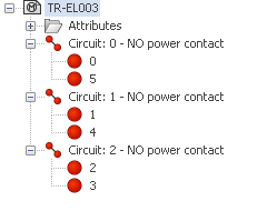
The circuits are numbered from 0 to "n", generally from left
to right (or top to bottom) in relation to the symbol insertion point.
The software manages several types of circuits, corresponding
to the type of electrical component.
The symbol circuits must match the circuits of the manufacturer
part to be associated with the symbol.

|
Menu: Edit symbol >
New circuit |
Opens a dialog box letting you select the circuit characteristics.
Number: Enter the number
of circuits you want to add.
Circuit type: Select the type
of circuit. The list depends on the class of the symbol. To access the
entire circuit list, select the More
circuit types.
Information transmission: Defines
whether the circuit must allow certain information to pass through, such
as the phase or equipotential number.
Disconnectable:
(Only allows the phase number to pass).
Used on the majority of schematic symbols.
The equipotential number is different between the incoming and outgoing
connection points.
Passing:
(equipotential pass through symbols)
A passing circuit is a circuit where the
equipotential is continued between two connection points, but for each
point of the circuit, there is a distinct wire cabling order.
Hyper
passing: (equipotential pass through symbols)
A hyper passing circuit is used when you
wish to have the same equipotential wire number on two or more
different circuits using components that are linked and have an identical
circuit and connection point data (e.g. a busbar distribution block split
into segments. Wires does not go through circuits).
Hyper
hyper passing: (equipotential and wires pass through symbols)
A hyper hyper passing circuit connects up
two or more symbols with the same connection point details (e.g. screen
and will continue the equipotential between these points). The connection
points, however, are not detailed in connection reports as they are transparent
as if the wire is directly connected between the two end components. The
typical case is origin-destination arrows.
The properties of the circuit appear in the lower part of the dockable
panel.