SOLIDWORKS Electrical Schematic
- Exercise #13
In this exercise, you will learn how to manage several types of symbols,
such as wiring line diagram, or schematic symbols. You will create a PLC
symbol from its manufacturer part.
If this is your first time, open the PDF file of the exercise to read
through it. Printing it out is recommended.
Line diagram
symbol
Ensure that the Emergency stop
symbol is compatible for insertion into a line diagram drawing.
1. Open the Symbol
management.

|
Menu: Library > Symbol
management |
2. Click on the Filters
tab and fill in the fields.
3. Select the symbol for the emergency stop and click
on the Open icon (double-clicking
on the symbol works as well).

|
Symbol management: Open |
4. To make it compliant with line diagram symbol management,
simply place a rectangle around the symbol.

|
Menu:
Draw> Rectangle |
Without this rectangle, the wires / cables cannot snap onto
the symbol. |
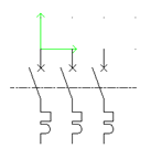
Schematic symbol
Create a new 3P thermal-magnetic circuit breaker-type symbol in compliance
with Appendix 13a. This symbol must:
-
Be named Training_Circuit_Breaker
- Belong to the
IEC library
- Be drawn using
Metric units
- Be declared
as a Parent in line symbol
- Be automatically
associated with the 21113
part from Schneider
- Propagate the
cross references, the current rating, and the magnetic current
setting |
1. Go into the Circuit
breakers / Thermal-magnetic class in the Classification
tab in the Symbol management.
2. Then click on the Filters
tab and select the criteria below.
3. You can also select a symbol in the right-hand
part of the dialog box.
4. Then click on the New
icon.

|
Symbol management: New |
5. Enter the properties as shown below.
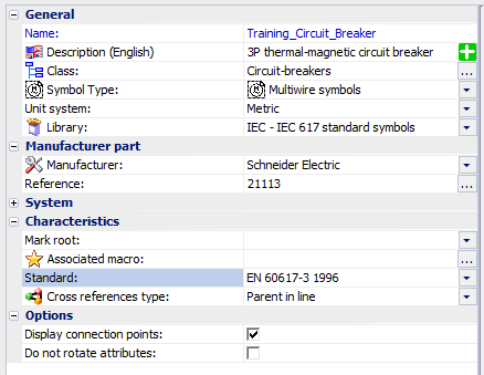
6. Click on the OK
button to create the symbol.
An empty thumbnail is automatically added in the right-hand
part of the dialog box. |
7. Select it and click on the Open
icon.
|
Symbol management: Open |
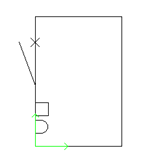
The Training_Circuit_Breaker
is open in the graphical interface. Here is some advice to help
you create the graphic using free tools. |
8. Insert a rectangle where the first point is at
coordinates (0,0) and the second at coordinates (10,15).
|
Menu:
Draw > Rectangle |
9. Draw the first pole of the circuit breaker, using
the rectangle to help you.

|
Menu:
Draw > Line |

|
Menu:
Draw > Arc |
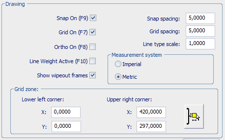
Next, set the snap spacing so the connection points are
placed at the same intervals as the distance between the wires
(5mm by default). |
10. Right-click in the lock bar (the bottom right
of the screen) to open the drawing support dialog box.
11. Set the snap and grid settings as shown opposite.
12. Then delete the rectangle.
13. Create poles 2 and 3 of the circuit breaker by
copying the first pole. With the snap spacing locked, the poles will be
equidistant at 5mm. Add the axis line.

|
Menu:
Modify > Multiple copy |
|
Menu:
Draw > Line |

|
Menu:
Modify > Properties |
14. Move the assembly so that the connection highest
and furthest to the left is on the axis marker (double green arrow on
coordinates (0,0)).

|
Menu:
Modify > Move |
15. Add 3 disconnectable Circuit
breaker/Switch type circuits.

|
Menu: Edit symbol >
New circuit |
16. To insert the connection points, select circuit
0 and click on the Connection point
icon in the Edit symbol menu.

|
Menu: Edit symbol >
Connection point |
The connection point block is attached to the cursor. It
is composed of a line and two circles. |
17. Press [Space]
to rotate the connection point.
18. Insert the connection point so that the white
circle coincides with the point the wire will connect to.
19. Insert the five other connection points, selecting
the corresponding circuits beforehand.
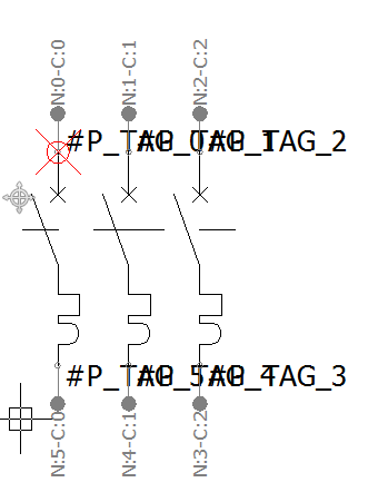
The dockable panel displays the properties of the connection
points, allowing any allocation errors to be corrected.
In each circuit, the number of the point in the upper part must
be less than the one in the lower part. |
20. To insert the attributes, click on the Attribute
insertion icon in the Edit symbol
menu.

|
Menu: Edit symbol >
Insert attribute |
21. In the Attributes management dialog box, check
the boxes for the attributes to be inserted on the symbols.
Identification
/ #TAG
Descriptive data
/ Cross references / #CROSS_REF
Descriptive data
/ Manufacturer data / #TD_1
Descriptive
data / Manufacturer data / #TD_4 |
22. Insert the attributes near the symbol.
The Properties command
of the attribute allows you to modify its font, height, and justification. |
23. Close and save the symbol file.
24. Check the result by inserting the symbol in a
scheme drawing.