SOLIDWORKS Electrical 3D
- Exercise #01
To do this exercise and the others, you have to download a electrical
project containing all the required environment. After the download, unarchive
the electrical project.
Click this link
to download the electrical project.
The goal of this exercise is to update a 3D assembly, to be compatible
with the SOLIDWORKS Electrical
3D process (cabinet layout and routing). A wizard helps you to manage
the connection points (to connect the cables or the wires), to define
the faces and to assign the mate reference to insert it on a rail.
It is based on the 3D part lc1d1210b7_ew.SLDPRT
stored in the Project folder (...\SOLIDWORKS Electrical\Projects\XX\SolidWorks - XX
must be replaced by the electrical project ID which you can find in the
Electrical project management.)
Defining the faces and
the mates
Creating the connection points
Defining the faces
and the rail mates
1. The first step is to open the lc1d1210b7_ew.SLDPRT
file.
2. Launch the Electrical
Component Wizard.

|
Menu: Tools >
SOLIDWOKS Electrical > Electrical
Component Wizard |
3. Select the Mate
Reference section.
4. To define the different faces of the 3D part, click
the Define faces button. This
allows you to set the component alignment.
5. Minimize the wizard to access the graphical
area.
5. For each selection zone, click the corresponding
face of the component.
6. After defining the four faces, click on the green
checkmark to validate.
7. In the wizard, select the Reference
Name option (For
Rail) and click the Add button
to define the mate reference.
8. Select the top face in reference with the rail.
9. Select the front face in reference with the rail.
10. Click on the green checkmark to validate.
Creating the connection
points
1. In the wizard, select the Routing
Functionality Points section.
To create the connection points for a 3D part, it is better
to use the definition of a manufacturer part which can be assigned
to this 3D part. |
2. Select the Point
Type option (CPoint from manufacturer
part) and click the Add button.
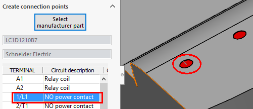
3. In the dockable panel, click the Select manufacturer part button.
4. In the Manufacturer
part search dialog box, search for the lc1d1210b7
manufacturer part from Schneider
Electric in the Contactor relays
class.
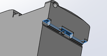
5. In the dockable panel, select the Terminal / Circuit
and click the corresponding component terminal in the graphical area.
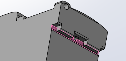
6. Validate each connection point by clicking on the
green checkmark.
7. Close the wizard and save the file in the SOLIDWORKS
folder of the electrical project.