You can simplify complex assemblies in several ways while seeking Simulation results if applicable. When the computational resources do not permit for simulation on the exact model, you can consider the following simplification options when working with assemblies or multi-bodies.
Keep in mind that the most accurate results are obtained by including all bodies in the assembly and using an optimal mesh size. Simplify assemblies only if you are confident that the simplification does not alter the problem you are trying to solve significantly.
Excluding parts from simulation
Use this option when you are interested only in the results for a portion of the assembly and you can estimate the effect of the excluded bodies by applying features on the rest of the bodies.
For example, consider the case when you exert a force shown below to hold the suitcase. If no other external forces are applied to the suitcase, then you can model the handle alone as shown. The objective of such a study could be to determine the optimal material and dimensions of the handle so that it does not fail.

If you are interested in the results on the suitcase body instead of the handle, you can remove the handle and apply the loads or restraints to the imprint of the handle on the suitcase body. An imprint is the common contact area that a body shares with another.
In general, it is better to exclude the bodies farther away from the component you are interested in than excluding those that are nearer. it is recommended to include the bodies that are close to important bodies unless you are confident that you can apply the proper effect.
Modeling components as remote loads, restraints, and masses
You can replace the bodies that you are not interested in by treating them as remote loads, restraints, and masses.
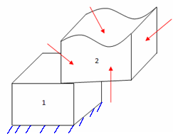
For certain models, it may be difficult to replace a body using remote loads, restraints or masses. As an example, in the figure below, even though you may not be interested in the results for body 2, you do not replace it.

You can exclude or replace a body with its effect if the following conditions are satisfied:
- The body itself is not of interest.
- Its effect on the rest of the bodies can be modeled correctly.
Treating components as rigid bodies
When you want to include the contact interactions between parts but save analysis time, you can treat certain components in the assembly as rigid. You can treat a body as rigid when it is much stiffer than its surrounding components or when the body is far away from the region of interest and the assembly is large. Treating components as rigid bodies leads to better approximation in the results than excluding them. For more details, see, Treat a Body as Rigid. The program meshes the outer boundary of a rigid body with shell elements to reduce simulation time.
Using connectors
By using connectors for modeling springs, pins, bolts, bearings, spot welds, edge welds, links, and rigid connections, you can reduce the number of elements in the mesh and save analysis time. For example, you can model shock absorbers in automotive suspensions using spring connectors instead of modeling the actual geometry. For details, see Connectors.
Using surface geometries, sheet metal bodies, and structural members to model the assembly
Surface geometries and sheet metal bodies mesh with shell elements and structural members mesh with one-dimensional beam elements. For more details, see Mesh types. Using them in the assembly wherever applicable can save analysis time by reducing the degrees of freedom. For example, you can consider replacing thin solid bodies with sheet metal bodies or surface geometries. For details, see Shell Modeling.
Simplifying Model for Meshing
You can simplify the assembly for meshing. In the Simulation study tree, right-click Mesh and select Simplify Model for Meshing. The Simplify utility determines an internal calculation of insignificant volume based on the size of the model. Supported features are listed in the task pane. You can suppress them and perform analysis on the simplified assembly.
Oversimplifying a model can produce erroneous results by altering the stress values significantly. You must not suppress features that produce high stresses in important bodies.
Improving approximate solutions from a coarse mesh
You can initially mesh the assembly with a Coarse Mesh Density, run the study, and obtain approximate results. As the next step, you can define another Simulation study and include only those components that you are interested in. For the second step, you can find out the contact forces that develop on the outer boundaries of the smaller model from the initial study and apply them to the study defined with the finer mesh.