Distributed coupling allows the faces attached to pin and bolt connectors
to deform, which delivers a more realistic representation of a connector’s behavior.
When you set Connection Type to
Distributed, a distributed coupling
formulation connects a reference node (beam element node of a bolt shank) to a group of
coupling nodes inside the imprint regions of a bolt's head and nut. Distributing
coupling constrains the motion of the coupling nodes to the translation and rotation of
the reference node. Nodes located inside the head and nut imprint areas can deform
relative to each other.
This constraint is enforced in an average sense in a way that enables control of the
transmission of loads through weight factors at the coupling nodes. For example, the
constraint distributes a bolt's pre-load such that the sum of the forces at the coupling
nodes is equivalent to the total pre-load at the reference node. Uniform weight factors
are applied in this case.
The distributed connection produces more realistic stress and
displacement fields at a bolt's head and nut contact areas.
A rigid connection produces stress hot spot areas inside the head and nut
regions of the connected components, because rigid bars introduce high stiffnesses. A
distributed connection eliminates these high stresses.
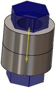
The image shows two cylindrical components connected by a bolt with a
prestress load of 1,000 N. No-penetration contact exists between the two
components.
