You can control the ply angle definition across different shells and faces using the Composite Orientation options.
Two models are shown where orientation options are used to change ply angle definition.
It is not recommended to change the default Mirror Orientation settings except for cases where there are inconsistencies in ply angle definitions. For re-defining ply angles consistently choose a non-zero, non-ninety degrees ply angle, example 60 degrees.
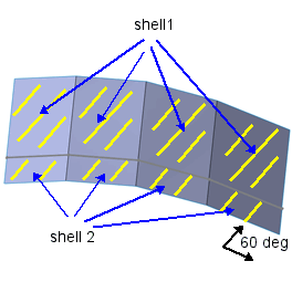
The model is composed of two shells with four faces each. To align the material orientations across all faces and shells consistently a ply angle of 60 degrees is selected in Composite shell plies table.
Desired ply angle orientation across shells and faces is shown below.
For the model, material orientation is consistent with desired orientation (white arrow) for shell 2 across every face.
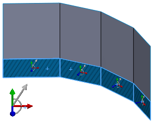
For shell 1, material orientation (white arrow) is inconsistent for every face (All blue arrows point into the plane).
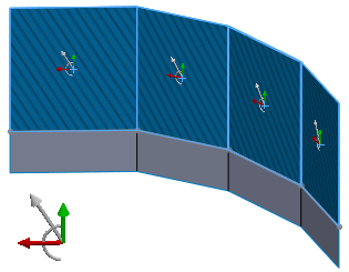
The Mirror Orientation option is toggled (unselected) for each face to get the desired orientation.
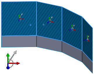
The blue arrows point in a consistent direction for all of the eight faces.
Make sure to check the mesh for consistency in the stacking direction across every face before running the analysis.
In this example, only rotate orientation option is required.
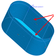
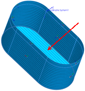
The model shown is a single shell with multiple faces. The blue arrows point outward for all of the faces indicating that the Mirror Orientation option need not be changed for any face.
In this case there is inconsistency in 0 degree reference ply angle for the bottom face. To remove inconsistency, the bottom face is selected and the Rotate Orientation option checked.
 |
 |
| Rotate option cleared for bottom face
|
Rotate option selected for bottom face |