SOLIDWORKS Electrical 3D
- Exercise #02
To do this exercise, you have to download an electrical project containing
all the required environment. After the download, unarchive the electrical
project.
The goal of this exercise is to implant the components in the cabinet.
Inserting the cabinet
Inserting the ducts and
the rails
Inserting the components
Inserting the cabinet
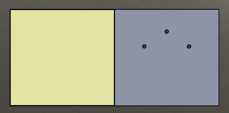
1. Once you unarchive the electrical project, double-click
it or use the contextual menu to open the Cabinet
assembly.
2. In the left dockable panel, select the 178864
manufacturer part assigned to the Cabinet, and select the Insert
command in its contextual menu.
3. Click the insertion point in the graphical
area.
Inserting the ducts
and the rails


|
Contextual menu of Rail (or Duct): Insert
as horizontal (vertical) rail (duct) |
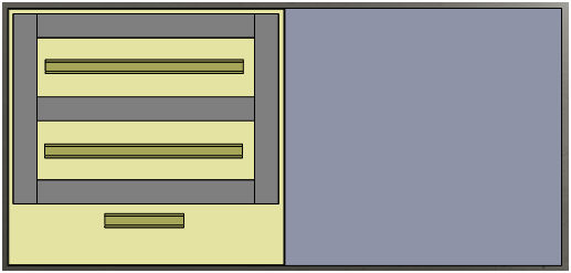
1. Start by inserting the ducts.
Insert the five ducts, using the contextual menu for each
reference. The first three references are for horizontal ducts,
and the last two are for vertical ducts.
During insertion, make sure that the point of insertion corresponds
to the back of the cabinet (the duct assembly has a mate coinciding
with the back of the cabinet). Validate the mate.
To do this exercise, the ducts have been sized with the desired
value (values stored in the properties of the reference). |
2. Manage the positioning mates.
3. Rails are inserted in the same way. The
rails for the electrical project are already sized. Insert them in order,
from top to bottom.
Inserting the components
Several commands are available to insert the components.
In this paragraph, you will see how they can be used. |
1. Insert the T1
component using the command Insert
available in the contextual menu.
To do the next step, you must do the Exercise
#01 to set the connection points, determine the faces
and the mates. If not, the 3D part will not be correctly inserted
and the wires will not be connected on the terminals. |
2. Insert the KM1 component
using the command Insert from file.
Select the lc1d1210b7_ew.SLDPRT
file stored in the folder of the electrical project. The 3D part must
have connection points and mate references, if not it will not be correctly
inserted in the rail and the wires will not be routed. (see the exercise
#01)
3. Select the Q1, Q2,
Q3 and Q4 components and
select the Insert command.
You can change the order of the insertion of the components.
In the left dockable panel, enter the distance between each 3D
part (10 mm). |
4. Insert the X1
terminal using the Insert terminals.
Like the previous command, you must enter the direction
of the insertion and the space between each terminal. |
5. Insert S1, S2, and
H1 using the Insert
command, on the Cabinet door and manage the mates.
There is another mode to manage the components: the Association mode. This mode
is used in Exercise #04. |