Managing components
A component represents an electrical device,
a PLC, a connector or a terminal. It is represented by
one or several symbols and has a mark. A component can be present in your
electrical project without having a graphical representation (no symbol
needs to be inserted into the drawings).
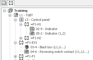
Components are listed in a specific tab on the dockable panel.
Double-click on a symbol of a component allows you to open the drawing
in which this symbol is inserted.
Displaying Components
If you need, you can use the [F5]
key or the Refresh command, in
the contextual menu of the electrical project, to refresh the component
list.
Several modes to display the component list are available in the contextual
menu of the electrical project, in the View
sub-menu.
Location view / Function view:
This mode allows you to display the components grouped by location or
by function.
Child components by hierarchy / Child
components in real location (function): This option allows you
to display a child component under its parent, or under its real location
(function) when the location (function) of the child component is different
from that its parent.
Sort by function (location) / Sort
by mark: Allows you to sort the components by the mark or by the
location (function).
In terminal strip and PLC, sort by
position / Always sort by mark: This option impacts only PLC and
terminal strips. It allows you to sort the sub-components of a terminal
strip or a PLC, by the mark or the position.
Hide accessory terminals:
Allows you to hide the accessories terminals.
Add a new component
A component can be added from a location contextual menu, or from existing
components (where one component is dependent on another).
Create a new component

|
Component: If you
select the Component option,
only one mark will be added (if you have not selected a manufacturer
part). |
The component properties dialog box is displayed, letting you manage
the component mark and if you want to assign it to a manufacturer part.
Create a new component from a manufacturer part
|
Component
manufacturer part: Selecting the Manufacturer
part option opens a dialog box where you can select
a manufacturer part. |
Refer to the Allocating
a manufacturer part section for more information about this dialog
box.
According to the equipment chosen and especially the classification
it relates to, a mark is automatically generated and added to the components
list.
You can also manage the number of components you want to create. At
the Manufacturer part selection
dialog box closure, enter the number of components and validate.
To create a new component, you can click OK
(Continue), the Manufacturer part
selection dialog box re-opens to search a new manufacturer part.
Set as permanent component
Generally, when all the graphical
elements (symbol, 2D footprint) are deleted, the component is removed.
You can activate a special property on the component to keep it in the
component list.

|
The command to access this permanent component setting is
available in its contextual menu. The icon is different on components
with the option enabled. |
Delete component

|
The delete command is available through the component contextual
menu. |
A component inserted into a drawing cannot be deleted.
Component properties

|
A component can be modified by using the contextual menu
Properties command or
the Properties of the component
for a symbol. |
It gives you access to the component
properties dialog, where you can modify the mark and associate manufacturer
parts.