You can use the Symmetry boundary
condition to create and analyze cavity and runner layouts that are symmetric about one or
two planes of symmetry. While the simulation runs only for the symmetric portion of the
layout, saving you time, SOLIDWORKS Plastics displays the results for the complete
layout.
To open the Symmetry PropertyManager:
- In the Plastics CommandManager, expand , and click Symmetry
 .
.
Surfaces identified as Symmetry
Faces behave as though they are thermally insulated, which prevents
heat loss through them. When using the Symmetry
boundary condition, ensure that the mold cooling layouts produce
symmetric mold temperatures. In the absence of symmetric mold temperatures, include
the complete cavity and runner layout along with the mold cooling channels for
accurate simulations.
The Symmetry boundary condition is available with
SOLIDWORKS Plastics Professional and SOLIDWORKS Plastics Premium.
Use caution when interpreting results from a simulation with a Symmetry boundary condition.
Parameters
| |
Along
solid body or Along
sketch-based runner
|
Specifies the
type of geometry to apply a symmetry boundary condition. Default selection for cavity and runner domains:
Along solid
body.
To specify symmetry
faces on sketch-based runner domains, select Along sketch-based runner.
|
 |
Symmetry 1 |
Specifies faces of a cavity or runner domain that
correspond to one plane of symmetry.
Selected faces highlight in blue in the graphics
area.
|
|
Symmetry 2 |
Specifies faces of a cavity or runner domain that
correspond to the second plane of symmetry.
Selected faces highlight in blue in the graphics
area.
|
| |
Show
preview
|
Displays a wireframe geometry of
the complete cavity or runner domain in the graphics area. Confirm that the complete layout is accurate
before proceeding with the simulation.
|
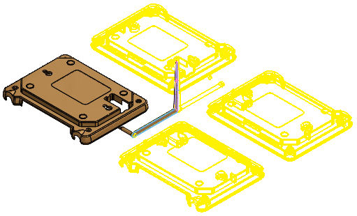 |
| Preview
of a cavity and runner design that is symmetric about two planes of
symmetry.
The
geometry
type
is
set
to Along solid
body. |