| Configuration name |
The name of the geometry configuration used to create
the mesh. |
| Mesh type |
Solid or
Shell |
| Meshing method |
Manual or
Automatic |
| Triangle size |
Global triangle size used for the mesh creation.
Locally, the triangle size may be finer than this due to refinement
based on curvature or local geometry entity selection. |
| Mesh tolerance |
The minimum allowable element size for automatic
refinement is given by the default value of triangle size multiplied
by the value of mesh tolerance. Mesh Tolerance is visible only
when you apply Curvature-based refinement.
|
| Total nodes of surface
mesh |
The total number of nodes (mesh vertices) of the
surface mesh. |
| Total elements of surface
mesh |
The total number of elements (mesh faces) of the
surface mesh. |
| Total nodes of solid
mesh |
The total number of nodes (mesh vertices) of the
solid mesh. |
| Total elements of solid
mesh |
The total number of polyhedral elements of the
solid mesh. |
|
Waterproof
|
|
Yes
|
The surface mesh is waterproof with no holes.
|
|
No
|
The surface mesh contains free edges.
|
|
| Number of Mesh
Group
|
Identifies the number of distinct meshed domains in a
model. For example, if you identified a geometric
body as a cavity and you add a runner, the number of mesh groups
is two. You can have two mesh groups for a single part when the
part has two distinct bodies that are not merged.
|
| Element
Intersections
|
Identifies where elements overlap. The software fails
to create a solid mesh when intersection elements exist. |
| Non-manifold |
Identifies elements that share a boundary with more
than two elements.
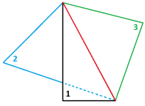 |
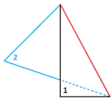 |
| Non-manifold elements. Three triangles share a
common edge (red). |
Manifold
elements. Two triangles share a common edge
(red). |
|
| Bad Elements
|
Shows the percentage of distorted elements with poor
aspect ratios over the total number of mesh elements. Elements with an aspect ratio between 8 and 20
are characterized as Bad
Elements.
Consider fixing
these elements, especially when the percentage number exceeds
15.
|
| Very Bad
Elements |
Shows the percentage of very bad
elements over the total number of mesh elements. Elements with an aspect ratio above 20 are characterized as
Very Bad Elements.
|
| Maximum Aspect
Ratio |
Shows the maximum aspect ratio in a model. The aspect ratio of an element is the ratio of
the longest edge to the shortest edge of a triangle. By
definition, the aspect ratio of a perfect triangle element is
1.0. A higher aspect ratio indicates poorer element
quality.
|
| Unmatched
Elements |
Identifies elements at the boundaries of geometric
entities that touch or intersect but do not share common nodes. In
these cases, the mesh is considered incompatible due to unmatched
elements. Such errors are common with insert molding or overmolding
where two domains meet. In compatible meshes, the
entities that touch have a node-to-node correspondence between
their meshes at the boundaries.
|
| Computer name
|
The name of the computer that generated the
mesh. |