Gtol Frame XML Schema
Gtol frame symbol XML structure
The Gtol frame XML schema definition (*.xsd)
file is located in install_dir\data\xmlschema.
SOLIDWORKS uses the XML schema definition file to validate the symbol
XML file that is passed to
IGtolFrame::SetSymbolXml.
The Gtol frame symbol XML file has the following node structure. The top level node is
<GtolFrame>, and sub-nodes are indented below it. If a node is missing
in an XML file, the corresponding category has all default values. For more information about geometric tolerance symbols and
their values, see the SOLIDWORKS user-interface help > Detailing and
Drawings > Annotations > Symbols > Geometric Tolerance Symbols > Tolerance
Dialog Box topics. If you are new to XML, see
XML Tutorial.
<GtolFrame>
<ToleranceSymbol> Mandatory.
Value: forty-four possible strings or empty if this frame is a composite with
the previous frame. See the Tolerance dialog section in
Gtol Frame symbol XML node to user interface mapping.
<ToleranceRangeInfo>
<PrimaryToleranceValue> Mandatory. Values: numerical
<PrimaryRangeSymbol> Optional. Values: phi/sPhi/sqr,
where phi = diameter, sPhi = spherical diameter, sqr = square
<ConjunctionSymbol1> Optional. Values: dash “-“ or slash “/”
<ToleranceZone> Optional. Values: numerical
<ToleranceZoneSymbol> Optional. Values: phi/sPhi/sqr/deg,
where deg = angle degree
<ConjunctionSymbol2> Optional. Values: dash “-“ or “X”
<RestrictedToleranceZoneLimit> Optional. Values: numerical
<RestrictedToleranceZoneLimitSymbol> Optional. Values: phi/sPhi/sqr/deg
<ApplyMAXTolerance> Optional. Values: true/false
<MaxToleranceSymbol> Optional. Values: phi
<MaxToleranceValue> Optional. Values: numerical
<OffsetZoneInfo>
<UnequallyDisposedProfile> /
<ToleranceZoneOffset> Optional. Specify one of these
two nodes.
See below
<UnequallyDisposedProfile>
<OutsideDisposition>
Optional. Values: numerical
<ToleranceZoneOffset>
<OutsideFirstZoneOffset> /
<InsideFirstZoneOffset>
<FirstOffset> Optional.
Values: numerical
<OutsideSecondZoneOffset> /
<InsideSecondZoneOffset> Optional. Specify one of these
two nodes. Values: true/false
<SecondOffset> Optional. Values: numerical
<DynamicProfile> Optional. Values: true/false
<Combination> Optional. Values: CZ/SZ
<Constraint>
Optional. Specify up to three of these nodes. Values: OffsetToleranceZone|UnspecifiedAngularToleranceZoneOffset|OrientationOnly
<FeatureInfo>
<Filters>
<FilterDetail> Unlimited number of these nodes
<FilterSymbol>
Values: G/S/SW/CW/RG/RS/OB/OH/OD/CB/CH/CD/AB/AH/AD/F/H
<ShortWavePassFilter> Optional. Values: true/false
<CutOff> Optional. Values: numerical
<LongWavePassFilter>
Optional. Values: true/false
<FilterIndicationSeparator> Optional. Values: space/X or empty
<ShortWavePassFilter2> Optional. Values: true/false
<CutOff2> Optional. Values: numerical
<LongWavePassFilter2> Optional. Values: true/false
<AssociatedFeatureInfo> Optional. Values: Minimax / LeastSquares / MinimumCircumscribed / Tangent /
MaximumInscribed
<ProjectedToleranceZone>
Optional. Values: true/false
<Projection> Optional. Values: numerical
<ProjectionRange> Optional. Values: numerical
<DerivedFeatureForFeatureOfSize> Optional. Values: true/false
<AssociatedCharacteristic> Optional. Values: C/CE/CI/G/GE/GI/X/N or empty
<ParametricCharacteristic> Optional. Values: P/V/T/Q or empty
<MaterialCondition> Optional.
<MaximumMaterialCondition> Optional. Values: true/false
<LeastMaterialCondition> Optional. Values: true/false
<ReciprocityRequirement> Optional. Values: true/false
<RegardlessToFeatureSize> Optional. Values: true/false Valid only if <MaximumMaterialCondition> or <LeastMaterialCondition>
is specified
<StateSymbol> Optional. Values: true/false
<StatisticalSymbol> Optional. Values: true/false
<DatumCompartment> Optional.
Specify up to three of these nodes
<TranslationConstraintAlongXAxis> Optional. Values: true/false
<TranslationConstraintAlongYAxis> Optional. Values: true/false
<TranslationConstraintAlongZAxis> Optional. Values: true/false
<RotationalConstraintAlongXAxis> Optional. Values: true/false
<RotationalConstraintAlongYAxis> Optional. Values: true/false
<RotationalConstraintAlongZAxis> Optional. Values: true/false
<ContactFeature> Optional. Values: true/false
<OrientationDegreesOfFreedomOnly> Optional. Values: true/false
<VariableLinearDistanceWithinACollectionOfFeatures> Optional.
Values: true/false
<Translation> Optional. Values: true/false
<TranslationValueI> Optional. Values: numerical
<TranslationValueJ> Optional. Values: numerical
<TranslationValueK> Optional. Values: numerical
<DatumDetail> /
<Datums> Specify one of these two nodes. See below
<Datums>
<DatumDetail>/<Datums> Any number of either of these nodes
<SubDatums>
<DatumDetail> Any number of these nodes
<DatumDetail>
<DatumLetter> Values: text
<PlaneSituationFeature> Optional. Values: true/false
<StraightLineSituationFeature> Optional. Values: true/false
<PointSituationFeature> Optional. Values: true/false
<AnyCrossSection> Optional. Values: true/false
<AnyLongitudinalSection> Optional. Values: true/false
<FeatureProjection> Optional. Values: true/false
<Projection> Optional. Values: numerical
<DatumMaterialCondition> Optional. Values: MaximumMaterialCondition/ LeastMaterialCondition/
RegardlessToFeatureSize
<FreeState> Optional. Values: true/false
Gtol frame symbol XML node to user interface mapping
Tolerance dialog
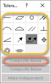
The Tolerance dialog above appears when a
Gtol symbol is placed in the graphics area. The symbols inside the yellow
oval each map to Gtol XML <ToleranceSymbol>. In SOLIDWORKS, each of these
tolerance symbols is defined in C:\ProgramData\SolidWorks\SolidWorks
20nn\lang\english\gtol.sym. Using
the Gtol API, you can specify 42 different tolerance symbols (14 tolerance
symbols (ANGULAR, CIRC, CONC, CYL, FLAT, LPROF, PARA, PERP, POSI, SPROF, SRUN,
STRAIGHT, SYMMETRY, TRUN) in each of three libraries: GTOL, IGTOL, and
GGTOL). You can specify two additional tolerance symbols using the GGTOL
library: LONG, AXIS. Inspect the GTOL, IGTOL, and GGTOL libraries in
gtol.sym and specify the XML geometric tolerance symbol name in
LibraryName-SymbolName format.
Internally, SOLIDWORKS formats the tolerance symbol with angle brackets: <LibraryName-SymbolName>.
<IGTOL-FLAT> (Flatness tolerance symbol (*FLAT) in the ISO Geometric Tolerancing
library (IGTOL) of gtol.sym)
You must remove the angle brackets when specifying the
flatness symbol in the Gtol XML string:
<ToleranceSymbol>IGTOL-FLAT</ToleranceSymbol>
If a frame is a composite with the frame above it,
<ToleranceSymbol> for the second frame is empty:
<ToleranceSymbol></ToleranceSymbol> for frame 2
means that frame 1 and 2 are composites.
In Gtol  the first frame has XML string <ToleranceSymbol>IGTOL-FLAT</ToleranceSymbol>
and second frame has XML string <ToleranceSymbol></ToleranceSymbol>.
the first frame has XML string <ToleranceSymbol>IGTOL-FLAT</ToleranceSymbol>
and second frame has XML string <ToleranceSymbol></ToleranceSymbol>.
Range
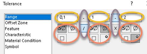
A Tolerance options dialog above appears when a tolerance symbol is selected
in the Tolerance dialog and the Gtol is placed in the graphics area. The Range information in
the picture above maps to XML node <ToleranceRangeInfo> and its sub-nodes.
The ovals
are numbered and colored in a top to bottom, left to right fashion as follows: 1 (yellow), 2 (red), 3 (purple), 4 (yellow), 5 (red), 6 (purple), 7 (yellow), 8
(red).
Yellow oval 1 maps to XML node <PrimaryToleranceValue> which has a numerical value.
Red oval 2 maps to XML node
<PrimaryRangeSymbol>, with possible values sPhi (for spherical diameter),
phi (diameter), sqr (square), or empty for none.
Purple oval 3 maps to XML node
<ConjunctionSymbol1>, with possible values -, /, or empty for neither.
Yellow oval 4 maps to XML node <ToleranceZone>
which has a numerical value.
Red oval 5 maps to XML node <ToleranceZoneSymbol>, with
possible values sPhi (for spherical diameter), phi
(diameter), sqr (square), deg (degree), or empty for none.
Purple oval 6 maps to XML node <ConjunctionSymbol2> with values -
or X (no empty value option
here).
Yellow oval 7 maps to XML node <RestrictedToleranceZoneLimit> has a numerical value.
Red oval 8 maps to XML node <RestrictedToleranceZoneLimitSymbol> with
possible values sPhi (for spherical
diameter), phi (diameter), sqr (square), deg (degree), or empty for none.
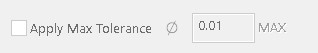
Apply Max Tolerance control maps to XML node <ApplyMAXTolerance> with
possible values true or false. If Apply Max Tolerance is selected in the dialog,
the max tolerance symbol and value controls are enabled.
Max tolerance symbol control maps to XML node <MaxToleranceSymbol> with
possible value of phi (diameter).
Max tolerance value control maps to XML node <MaxToleranceValue> with
possible numerical values.
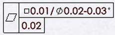
The first frame in the above Gtol has Range XML string:
<ToleranceRangeInfo>
<PrimaryToleranceValue>0.01</PrimaryToleranceValue>
<PrimaryRangeSymbol>sqr</PrimaryRangeSymbol>
<ConjunctionSymbol1>/</ConjunctionSymbol1>
<ToleranceZone>0.02</ToleranceZone>
<ToleranceZoneSymbol>phi</ToleranceZoneSymbol>
<ConjunctionSymbol2>-</ConjunctionSymbol2>
<RestrictedToleranceZoneLimit>0.03</RestrictedToleranceZoneLimit>
<RestrictedToleranceZoneLimitSymbol>deg</RestrictedToleranceZoneLimitSymbol>
</ToleranceRangeInfo>
The second frame has Range XML string:
<ToleranceRangeInfo>
<PrimaryToleranceValue>0.02</PrimaryToleranceValue>
<PrimaryRangeSymbol></PrimaryRangeSymbol>
</ToleranceRangeInfo>
Offset Zone
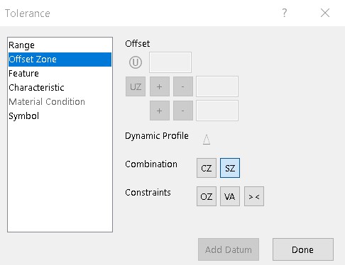
A Tolerance options dialog above appears when a tolerance symbol is selected
in the Tolerance dialog and the Gtol is placed in the graphics area. The Offset Zone information in the
picture above maps to XML node <OffsetZoneInfo> and its
sub-nodes.
In the first row, the circle-U control maps to Gtol XML
node <UnequallyDisposedProfile >. Setting its value to true is analogous to clicking that
control. The edit field control next to circle-U
maps to Gtol XML node <OutsideDeposition> which takes a numerical value.
The UZ control in the second row
maps to Gtol XML node <ToleranceZoneOffset>.
Setting its value to true is analogous to clicking that
control.
The +/- controls next to UZ
map to Gtol XML nodes <OutsideFirstZoneOffset> and
<InsideFirstZoneOffset>. Setting each to true is analogous to clicking those controls. The last edit value field on the
UZ line maps to Gtol XML node <FirstOffset> which takes a numerical value.
The next line’s +/- controls map to Gtol XML nodes <OutsideSecondZoneOffset> and
<InsideSecondZoneOffset>. Set each to true to
click those controls. The last edit value field on the
line maps to Gtol XML node <SecondOffset> which
takes a numerical value.
<UnequallyDisposedProfile> and <ToleranceZoneOffset> are mutually exclusive.
The Dynamic Profile control maps to Gtol XML node
<DynamicProfile> with possible values, true or false.
The Combination controls map to Gtol XML node <Combination>
with possible values CZ or SZ, but not both.
The Constraint controls (OZ
(Offset Tolerance Zone), VA (Unspecified Angular Tolerance Zone Offset
Specification Element), >< (Orientation-only Specification Element)) map to Gtol
XML node <Constraint> with possible values
OffsetToleranceZone / UnspecifiedAngularToleranceZoneOffset / OrientationOnly.
Specify one, two, or all three.
Gtol
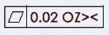 has the following Offset Zone XML string:
<OffsetZoneInfo>
<Constraint>OffsetToleranceZone</Constraint>
<Constraint>OrientationOnly</Constraint>
</OffsetZoneInfo>
Feature
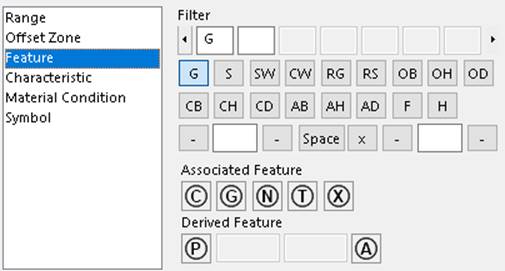
A Tolerance options dialog above appears when a tolerance symbol is selected
in the Tolerance dialog and the Gtol is placed in the graphics area. The Feature information in the
picture above maps to XML node <FeatureInfo> and its
sub-nodes.
The top four rows define multiple filters. The filter types are listed in the second
and third rows. Each filter type has associated information in the fourth row.
The information about a filter
type (as shown in an edit box in the top row) maps to Gtol XML node
<FilterDetail>. Since there could be many <FilterDetail> elements, <Filters> contains an
array of <FilterDetail>.
The 17 controls in the second and third rows of the dialog
map to Gtol XML node <FilterSymbol>.
There are seven controls in the fourth row of the dialog. The first three controls correspond to the first
cutoff value, with possible short/long wave dashes around it. The middle control
is a separator value that can be a space or an X. The last three controls
correspond to the second cutoff value, with possible short/long wave dashes
around it.
The fourth row of controls in the
Gtol, 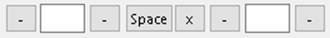 map (from left to right) to the following Gtol XML nodes:
<ShortWavePassFilter> true/false, analogous to setting/unsetting the first dash
<CutOff> numerical value
<LongWavePassFilter> true/false, analogous to setting/unsetting the second dash
<FilterIndicationSeparator> Three possible values: space, "X", or empty. If
empty, no space or X is added between cutoff and cutoff2 strings
<ShortWavePassFilter2> true/false, analogous to setting/unsetting the first dash
<CutOff2> numerical value
<LongWavePassFilter2> true/false, analogous to setting/unsetting the second dash
Gtol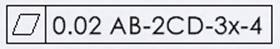 has two filters of type AB and CD. “AB-2” is filter 1
and “CD-3x-4” is filter 2. The filter portion of its XML string:
has two filters of type AB and CD. “AB-2” is filter 1
and “CD-3x-4” is filter 2. The filter portion of its XML string:
<Filters>
<FilterDetail>
<FilterSymbol>AB</FilterSymbol>
<CutOff>1</CutOff>
<LongWavePassFilter>true</LongWavePassFilter>
<FilterIndicationSeparator></FilterIndicationSeparator>
<CutOff2>2</CutOff2>
<LongWavePassFilter2>true</LongWavePassFilter2>
</FilterDetail>
<FilterDetail>
<FilterSymbol>CD</FilterSymbol>
<ShortWavePassFilter>true</ShortWavePassFilter>
<CutOff>3</CutOff>
<FilterIndicationSeparator>X</FilterIndicationSeparator>
<ShortWavePassFilter2>true</ShortWavePassFilter2>
<CutOff2>4</CutOff2>
</FilterDetail>
</Filters>
The row of Associated Feature controls 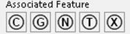 map to Gtol XML node <AssociatedFeatureInfo>. This node has five
possible mutually exclusive string values (corresponding to the five controls from left to right) “Minimax /
LeastSquares / MinimumCircumscribed / Tangent / MaximumInscribed”.
map to Gtol XML node <AssociatedFeatureInfo>. This node has five
possible mutually exclusive string values (corresponding to the five controls from left to right) “Minimax /
LeastSquares / MinimumCircumscribed / Tangent / MaximumInscribed”.
<AssociatedFeatureInfo></AssociatedFeatureInfo>
is analogous to de-selecting all five controls.
The 4 controls in the last row,
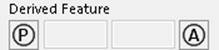 map to the following Gtol XML nodes:
<ProjectedToleranceZone> true/false, analogous to clicking/unclicking the  control
<Projection> numerical value
<ProjectionRange> numerical value
<DerivedFeatureForFeatureOfSize> true/false,
analogous to
clicking/unclicking the
 control
Characteristic
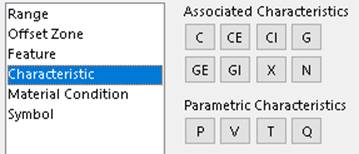
A Tolerance options dialog above appears when a tolerance symbol is selected
in the Tolerance dialog and the Gtol is placed in the graphics area. The Characteristic information in
the picture above maps to Gtol XML nodes:
<AssociatedCharacteristic> has mutually exclusive values, C, CE, CI, G, GE, GI,
X, N, or empty
<ParametricCharacteristic> has mutually exclusive values, P, V, T, Q, or empty
Material Condition
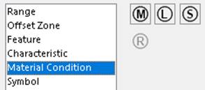
A Tolerance options dialog above appears when a tolerance symbol is selected
in the Tolerance dialog and the Gtol is placed in the graphics area. The Material Condition information
in the picture above maps to XML node <MaterialCondition> and its four
sub-nodes. All of these nodes have true/false values. Setting a node to true
is analogous to clicking the control in the user interface.
<MaximumMaterialCondition> 
<LeastMaterialCondition>

<ReciprocityRequirement>

<RegardlessToFeatureSize>

Gtol
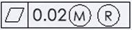 has the following Material Condition XML string:
<MaterialCondition>
<MaximumMaterialCondition>true</MaximumMaterialCondition>
<ReciprocityRequirement>true</ReciprocityRequirement>
</MaterialCondition>
Only M, L, S,
MR, and LR are allowed. No other combinations are permitted.
Symbol
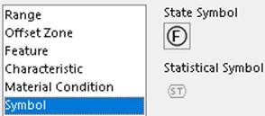
A Tolerance options dialog above appears when a tolerance symbol is selected
in the Tolerance dialog and the Gtol is placed in the graphics area.The Symbol information in the
picture above maps to XML nodes <StateSymbol> and <StatisticalSymbol>. Both have
true/false values. Set each to true to click the corresponding control.
Datum dialog
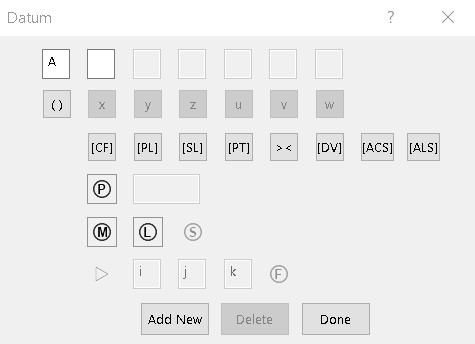
The Datum dialog above appears when you
click Add Datum in the Tolerance Options dialog box.
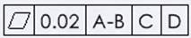
Each of the 3 datums (A-B, C, D)
maps to Gtol XML node <DatumCompartment> and sub-nodes <DatumDetail> and
<DatumLetter>. Each datum compartment can have a
single datum letter, like C or D, or it can have a datum group
(A-B) as in the Gtol above. A datum compartment can also have a sub-datum group
(C-D) which maps to Gtol XML node <SubDatums> and its sub-nodes.
Gtol
 has the following Gtol XML string:
<DatumCompartment>
<Datums>
<DatumDetail>
<DatumLetter>A</DatumLetter>
</DatumDetail>
<DatumDetail>
<DatumLetter>B</DatumLetter>
</DatumDetail>
<SubDatums>
<DatumDetail>
<DatumLetter>C</DatumLetter>
</DatumDetail>
<DatumDetail>
<DatumLetter>D</DatumLetter>
</DatumDetail>
</SubDatums>
</Datums>
</DatumCompartment>
<DatumCompartment>
<Datums>
<DatumDetail>
<DatumLetter>E</DatumLetter>
</DatumDetail>
</Datums>
</DatumCompartment>
<DatumCompartment>
<Datums>
<DatumDetail>
<DatumLetter>F</DatumLetter>
</DatumDetail>
</Datums>
</DatumCompartment>
The datum letters are listed in the top row of the Datum
dialog. The next five rows of 23 controls are associated with each datum letter,
with 13 exceptions. The 13 exceptions
are controls x,y,z,u,v,w,[CF], ><, [DV], triangle symbol, i, j, and k. These
13
controls apply to the whole datum compartment and display at the end of the
datum compartment. They all have true/false values.
The 13 user-interface controls that apply to the entire datum compartment
map to Gtol XML nodes as follows:
<TranslationConstraintAlongXAxis> - x
<TranslationConstraintAlongYAxis> - y
<TranslationConstraintAlongZAxis> - z
<RotationalConstraintAlongXAxis> - u
<RotationalConstraintAlongYAxis> - v
<RotationalConstraintAlongZAxis> - w
<ContactFeature> - [CF]
<OrientationDegreesOfFreedomOnly> - ><
<VariableLinearDistanceWithinACollectionOfFeatures> - [DV]
<Translation> - triangle symbol

<TranslationValueI> - i
<TranslationValueJ> - j
<TranslationValueK> - k
The other ten controls pertain to a datum letter
and are listed under the node <DatumDetail> for that datum letter. The
ten datum user-interface controls map to Gtol XML nodes as follows:
<DatumLetter> - string value for datum letter displayed in the edit
box in the top row of the Datum dialog
<PlaneSituationFeature> -[PL]
<StraightLineSituationFeature> -[SL]
<PointSituationFeature> -[PT]
<AnyCrossSection> - [ACS]
<AnyLongitudinalSection> - [ALS]
<FeatureProjection> -
<Projection> - the edit box next to feature projection in the
Datum dialog
<DatumMaterialCondition> - 3 possible values MaximumMaterialCondition / LeastMaterialCondition / RegardlessToFeatureSize
<FreeState> -

The second datum compartment
of this Gtol  has the following Gtol XML string:
<DatumCompartment>
<TranslationConstraintAlongXAxis>true</TranslationConstraintAlongXAxis>
<TranslationConstraintAlongYAxis>true</TranslationConstraintAlongYAxis>
<ContactFeature>true</ContactFeature>
<VariableLinearDistanceWithinACollectionOfFeatures>true</VariableLinearDistanceWithinACollectionOfFeatures>
<DatumDetail>
<DatumLetter>E</DatumLetter>
</DatumDetail>
</DatumCompartment>
The
last datum compartment of this Gtol  has the following Gtol XML string:
<DatumCompartment>
<DatumDetail>
<DatumLetter>G</DatumLetter>
<PlaneSituationFeature>true</PlaneSituationFeature>
<StraightLineSituationFeature>true</StraightLineSituationFeature>
<PointSituationFeature>true</PointSituationFeature>
<FeatureProjection>true</FeatureProjection>
<Projection>0.02</Projection>
<DatumMaterialCondition>LeastMaterialCondition</DatumMaterialCondition>
<FreeState>true</FreeState>
</DatumDetail>
</DatumCompartment>
When the datum compartment has more
than one datum letter, the node <Datums> contains a number of sub-nodes of type <DatumDetail>,
<SubDatums>, and <DatumLetter>.
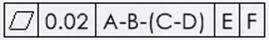
For this Gtol 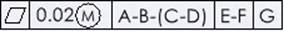 :
:
The first datum compartment has the following Gtol XML
string:
<DatumCompartment>
<Datums>
<DatumDetail>
<DatumLetter>A</DatumLetter>
</DatumDetail>
<DatumDetail>
<DatumLetter>B</DatumLetter>
</DatumDetail>
<SubDatums>
<DatumDetail>
<DatumLetter>C</DatumLetter>
</DatumDetail>
<DatumDetail>
<DatumLetter>D</DatumLetter>
</DatumDetail>
</SubDatums>
</Datums>
</DatumCompartment>
The second datum compartment has the following Gtol XML
string:
<DatumCompartment>
<Datums>
<DatumDetail>
<DatumLetter>E</DatumLetter>
</DatumDetail>
<DatumDetail>
<DatumLetter>F</DatumLetter>
</DatumDetail>
</Datums>
</DatumCompartment>
The third datum compartment has the following Gtol XML
string:
<DatumCompartment>
<DatumDetail>
<DatumLetter>G</DatumLetter>
</DatumDetail>
</DatumCompartment>