Numerical simulation uses discrete approximations of continuum mechanics.
Good
numerical
methods seek to balance accuracy,
robustness,
and performance.
The solid analysis procedure uses the finite volume method for Fill, Pack, and
Cool analyses. This is a discrete approximation that applies equally to the three
spatial dimensions. Results are more accurate when you use a fine mesh. However, you
might decide to use a coarser mesh to achieve a faster, though less accurate
solution.
The shell analysis procedure uses further numerical approximations to model the
cross-stream flow and the heat transfer without using a mesh that spans the
cross-stream direction. The shell analysis procedure applies primarily to thin parts
with essentially uniform thickness.
The shell analysis procedure uses two numerical approximations to model
laminar flow:
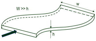
- Hele-Shaw flow for cavity domains
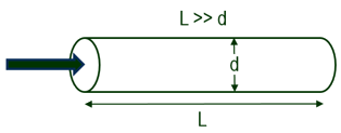
- Hagen-Poiseuille flow for runner domains
These approximations assume that the flow is always parallel to the solid
boundaries, which means that the shell analysis procedure cannot properly model
cross-stream flow. The shell analysis procedure is further limited to injection
processes that use a single polymer material.
| Hele-Shaw Flow for Shell Analysis |
Hagen-Poiseuille Flow for Shell Analysis |
 |
 |
| Laminar flow between two parallel flat plates
separated
by
a small gap |
Laminar flow in a long cylindrical tube |
The solid procedure typically requires a minimum of five mesh elements to span
a flow passage. To mesh a thin part, you typically need at least five to ten times more
solid mesh elements than shell elements. Judicious use of the shell procedure saves
computation time.
The shell procedure will be less accurate wherever the basic assumption—that
the flow is always parallel to the solid boundaries—is not valid. This can happen, for
example, when the flow impinges on the cavity wall opposite a valve gate, when jetting
occurs, or when a cavity flow encounters a protuberance or step change in thickness.
However, such inaccuracies might be local in nature
and
would have only small effects on the overall flow results. In
addition, even though the solid procedure might be able to capture some or all of these
effects, it also requires a fine enough mesh resolution to do so. Without sufficient
mesh refinement, the solid procedure might not be significantly more accurate than the
shell.
Recommendation: For accurate Cool and Warp analyses, use the solid
procedure.
Recommended Analysis Procedure Based on Part Geometry
| Part Geometry |
Example |
Shell Procedure |
Solid Procedure |
Comments |
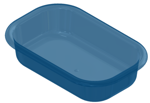
| Thin parts with few or no thickness variations |
 |
Yes |
Yes |
The shell procedure is most efficient for this type of
part. |
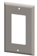
| Thin parts |
 |
Yes |
Yes |
The shell procedure can handle small
variations in thickness and some holes in the part. |
| Thick parts |
 |
No |
Yes |
|
| Parts with large thickness variations |
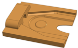 |
No |
Yes |
|
| Perforated plates |
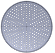 |
No |
Yes |
The shell mesh procedure is suitable only in
cases where the perforations are fewer or spaced far
apart. |
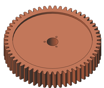
| Grids |
 |
No |
Yes |
|
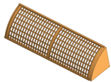
| Rings or frames |
 |
No |
Yes |
|
Supported Injection Processes for Solid and
Shell
Procedures
| Injection Process |
Solid Analysis Procedure |
Shell Analysis Procedure |
| Single Material |
Yes |
Yes |
| Single Material with Insert |
Yes |
No |
| Co-injection |
Yes |
No |
| Bi-injection |
Yes |
No |
| Gas-assist |
Yes |
No |
| Water-assist |
Yes |
No |