When a symbol is inserted on a wire, the wire is automatically cut on the right of
the symbol. In the same way, when the wire is placed over the symbol, it is automatically cut.
This is only possible if the symbol has connection points.
The connection points are placed so that they are superimposed on the wire when the
symbol is inserted. The connection points have an attribute allowing the number of
the manufacturer part material terminal to be propagated.
To access connection point, in the menu click
 .
.
There are three types of connection points:
- Connection point (By default). A connection point
used for all symbols other than polarity origin-destination.
- Incoming/outgoing connection point. These connection
points are directional (incoming / outgoing) and exclusively reserved for
symbols used for polarity origin-destination.
When inserting connection points, ensure that the SNAP option
is active and the resolution pitch is compatible with the distance separating the
symbol's circuits, as well as the distance separating two wires (Example: two phases
of a power wire).
The connection points are positioned where the symbol must cut the wire.
To insert a connection point:
- Select the circuit that the connection point belongs to in the dockable
panel.
- Select the command in the menu.
- Turn the connection point in the right direction (press Spacebar
on the keyboard to rotate the connection point according to the
angle of the wire).
- Click the insertion point for the connection point in the graphical
area.
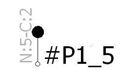
A message appears informing you when the connection point has been inserted
(
N:0-C:0). The number after the
C
is the circuit number. The number after the
N is the order
number in the circuit.

The value allocated to N is not important; you can have
N:6 even if the circuit has only two connection points.
All values for N for a given circuit must be compared. The
program then classifies all the connection points for the circuit according to the
value of N.
For a circuit C1, you can have N:1 and
N:4. N:1 is the first connection
point in the circuit, and N:4 is the second. When the
manufacturer part is allocated, the same principle is used when allocating the
numbers on the material terminal. The number of the first material terminal will be
allocated to the first connection point on the circuit. The number of the second
material terminal will be allocated to the second connection point on the circuit,
and so on, for all the component's circuits.
A termination type can be associated with the connection point of the symbol, but if
you assign a manufacturer part on this symbol, the termination type of the
manufacturer part will be applied.
A contextual menu allows you to edit an existing connection point.
Multiple Connection Points
To access multiple connection point, in the menu click
 .
.
This command is similar to the connection point command except that circuits can be
created simultaneously, helping you place all connection points after
definition.
A dialog box opens that lets you add the circuits that belong to the symbol.
| |
|
Add
 |
Adds the circuits. |
Delete
 |
Deletes the selected circuits. |
Initialize from manufacturer
part
 |
Selects a manufacturer part with its circuit definition. This
manufacturer part can be associated with the symbol. |
Add the circuit type and indicate the quantity in the Number of
circuits field. Enter the number of terminals on the component, as
well as for each circuit. This data is automatically entered if you select a
manufacturer part. Click OK to confirm and exit the dialog
box.
The connection point is attached to the cursor. The connection points are placed one
after the other, according to the dockable panel instructions.