| Grid block |
The grid symbols are available in the symbol library.
Specific icons let you select, re edit the symbol. The data is
propagated into the attributes. |
| Title block |
Displays the title block in which the drawings will be drawn:
- Default title block: the title block associated with the
terminal strip drawings in the electrical project
configuration
- Title block specific to this configuration: all terminal strips
using this configuration are generated with this title
block
The bottom left-hand corner of the title block must be positioned
at the coordinates (0,0). All the layout parameters are moved, and based
on this point. Specific icons let you select and edit the page
layout. |
 |
Opens the Symbol selector to let
you change the symbol associated with the default symbol. |
 |
Removes the associated symbol. |
 |
Opens the Symbol editor to let
you modify the selected symbol. |
| General |
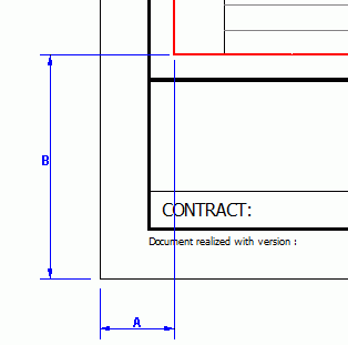 |
| A X coordinate |
Lets you manage the difference
A in X between the insertion point of the
grid block and the title block origin (0.0). |
| B Y coordinate |
Lets you manage the difference
B in Y between the insertion point of the
grid block and the title block origin (0.0). |
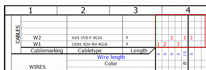
| Terminal strip orientation |
Defines the direction that generates the data for the
terminal strip representation. |
| Number of cores by drawing |
Defines the maximum number of cores that one drawing
may contain (number of columns on a horizontal terminal strip). |
| Number of cables on origin side |
Defines the number of cables managed in the Origin
part. |
| Number of cables on destination side |
Defines the number of cables managed in the
Destination part. |
SOLIDWORKS Electrical generates
terminals on a new drawing when at least one of these three parameters
(Number of cores per drawing, Number of cables on origin side, and
Number of cables on destination side) has reached the maximum value
defined in the configuration. |
| Formula to indicate connected cable core |
Opens the Formula management to define the parameters
of the cable core display text. |
 |