Refinement
Refinement settings determine how Composer tessellates (meshes)
the model, which affects model accuracy.
Set these options to achieve the best compromise between accuracy and file
size.
| Command Name
|
Description
|
| Relative
|
Specifies the triangulation method:
-
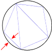
Chordal error - All geometry has the
same chordal error. Chordal error is the distance between the triangles that
define the geometry in Composer and the edges of the original geometry. When
you move the slider to
high quality, you decrease the chordal
error and increase the quality of the assembly.
In this image, the black circle is the original geometry.
The blue triangles define the geometry in Composer. The chordal error is the
distance represented by the red arrows.
-
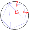
Normal deviation - All geometry has
the same normal deviation. Normal deviation is the angle between the normals of
the edges that define the triangular geometry of Composer. When you move the
slider to
high quality, you decrease the normal
deviation and increase the quality of the assembly.
In the image, the black circle is the original geometry.
The blue triangles define the geometry in Composer. The normal deviation is the
angle between the red arrows.
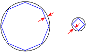
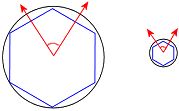
The difference between these two triangulation methods is
visible for scenes containing geometry of various sizes. Consider an assembly
of one very large cylinder and one very small cylinder.
With
Chordal error, because the chordal error
is constant, the polygon inscribing the large cylinder has many more sides.
This results in the geometry of the large cylinder looking better than the
small cylinder.
With
Normal deviation, because the normal
deviation is constant, the polygons inscribing both cylinders have the same
number of sides. This results in the geometry of the small cylinder looking
better than the large cylinder.
You can optimize the geometry degradation by moving the slider
between
high quality (for optimum triangulation
quality),
medium, and
low quality.
|
| Absolute (Advanced users only, use
carefully)
|
Defines the triangulation approximations.
You can set these three parameters independently. When you set
more than one, their effects are combined.
For each parameter, specify values that define the maximum
limits.
|
| Enable auto repair (healing is time
intensive)
|
Checks for missing triangles, incorrect holes in the mesh,
extra faces, and other discontinuity issues, and attempts to repair problems by
adding triangles. This option degrades import speed, so use only when
tessellation is poor. To import files without checking for incorrect geometry,
clear this option.
|
Occlusion
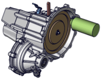
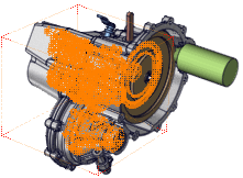
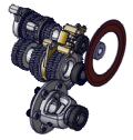
Occlusion removes parts from the model based on size or whether
the parts are internal and therefore not visible.
|
|
|
| Original Model
|
Internal Parts Detected
|
| Command Name
|
Description
|
| Remove small parts
|
Removes parts smaller than the specified percentage of the total
scene size. The calculation uses the volume of a bounding box, not the actual
part volume. For example, if you specify 10%, only parts that fit in a bounding
box that is 10% of the entire scene are removed.
|
| Remove internal parts
|
Removes parts that are internal and therefore not visible.
Applies to .smg, .smgXml, or .smgProj files
only.
|
| Apply to
|
(Available when
Remove internal parts is selected.) Runs
occlusion on:
-
Loading View
-
Views
-
Animation
-
All
Note:
Actors with opacity, displacement, or
texture-with-transparency property keys are not considered for occlusion.
|
| 3D
|
(Available when
Remove internal parts is selected.) Performs
occlusion on the 3D model. Snapshots are taken from different points of view.
For animation mode, snapshots are taken along the camera animation. Select one
of the following:
-
Speed - Uses fewer camera positions
resulting in faster computation.
-
Quality - Uses more camera positions.
To perform occlusion on the 2D view, clear this option.
|
| Cut triangles
|
(Available when
Remove internal parts is selected.) Runs
occlusion on actor triangles instead of actors. After analysis, you can remove
hidden triangles. Outlines remain visible until the file is reopened.
|
| Create Selection Set of Occluded Actors
|
Creates a single selection set composed of all the occluded
actors.
Note:
This option lets you check your result manually in Composer
after the conversion.
|
| Remove Occluded Actors
|
Deletes the occluded actors from the resulting Composer file
(output file).
|
SMG output
These options affect saved Composer files.
| Command Name | Description |
|---|
| Compression | Sets the amount of compression in files, which affects model tessellation quality.
-
Low (high quality) - 32 bytes/point, high measurement quality, large file
-
Medium - 16 bytes/point
-
High (low quality) - 8 bytes/point, low measurement quality, small file
The compression algorithm uses a bounding box defined by its coordinates: xmin, xmax, ymin, ymax, zmin, zmax. This bounding box is subdivided into a number of cubes according to the quality of compression selected:
- Low (high quality): 2^32 * 2^32 * 2^32
- Medium: 2^16 * 2^16 * 2^16
- High (low quality): 2^8 * 2^8 * 2^8
All tops (xi, yi, zi) of the triangulation are laid out on the tops of the cubes contained in the bounding box.
Notes:
When saving a file with medium or high compression, you should consider the following: - You cannot return to original quality. You must re-import your CAD files if you want to do so.
- Medium or high compression affects geometry precision. In the case of large parts where most of the precision is taken by the position of the object, little precision is left for elements such as small faces, lines or vertices.
- Medium or high compression might cause display issues (such as small holes visible in the mesh of a part, overlapping
faces, z-fight, appearance of undesired lines in technical
illustration, etc.) in vector output
generated by the Technical Illustration workshop.
To make it short, if geometry precision matters to you, it is recommended to use the Low (high quality) option.
| | Write normals | Saves normal directions for all faces in the file. Composer needs this information to display the outward or outside faces of parts and assemblies. When selected, file size is larger but file load time is shorter because Composer does not have to calculate this information.
A normal to a flat surface is a three-dimensional vector that is perpendicular to the surface. A normal to a non-flat surface at a point "p" on the surface is a vector that is perpendicular to the tangent plane to that surface at "p". | | Number of level of detail | Specifies how many levels of detail (LODs) are created and saved in
.smgGeom files for each geometry actor during translation. LOD specifies the actor mesh detail. For example, a screw can have a lower LOD in a car context than in an engine context.
This option works with the
Relative refinement option; the LOD value is the
Relative slider value divided by the LOD number:
-
1 - Creates one LOD using the
Relative slider value.
-
2 - Creates two LODs. For example, if
Relative is 0.8, the two LOD values are 0.8 and 0.4.
-
3 - Creates three LODs. For example, if
Relative is 0.8, the three LODs are 0.8, 0.4, and 0.26.
Notes:
-
Number of level of detail is ignored when the
Merge file into one actor per part import option is selected.
In Composer, the
Use level of detail option ([Default] Document Properties - Project) specifies what LOD to use when opening a project. You can also load individual parts specifying LOD; in the Assembly tree, right-click a part and select
.
|
|