| N/A | - Name
Specifies the actor name. This name appears in the Collaboration or Assembly tree and is the default tooltip text.
|
- Tooltip
Specifies the tooltip text that appears when you hover over the actor. The default is the actor name, but you can select a different property or meta-property, or type a text string. To type text, which itself can contain properties, select
String and use the
Tooltip string property.
Note:
By default, labels attached to an actor display the actor's tooltip text. To change this behavior, modify the label's
Text property.
|
- Tooltip string
(Available when
Tooltip is
String.) Specifies the tooltip text. Type your text, optionally with
property keywords. For geometry actors, click
 to display the
Text pane, where you can type multiple lines of text and more easily embed properties. to display the
Text pane, where you can type multiple lines of text and more easily embed properties.
See Text pane for details on property keywords and the Text pane.
|
- Color
- Specifies actor color. You can set color on both parts and assemblies.
Setting color at the assembly level can simplify color management and improves performance because Composer manages one color property instead of many. Parts inherit from the highest defined assembly color.
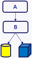
Assembly A = Undefined
Assembly B = Undefined
Part colors are displayed.
|
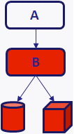
Assembly A = Undefined
Assembly B = Red
Part colors overridden by Assembly B.
|
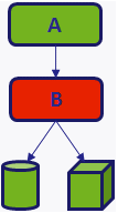
Assembly A = Green
Assembly B = Red
Part colors overridden by Assembly A.
|
- After specifying the actor color, if a color is inherited from the assembly, a message appears. Click Clear to clear the inherited color (and therefore, use the specified color), or click Cancel to keep using the inherited color.
Note:
You can choose to make the Clear behavior the default one by selecting the Don't ask this question again check box.
- To specify no assembly color, click
Undefined on the color palette.
Notes:
- Color interpolation is not performed when animating assembly actors with undefined color. When creating color property keys for assemblies, ensure that you specify colors.
Composer imports assembly-level color for the following formats: SOLIDWORKS and 3DXML.
- Composer does not support SOLIDWORKS occurrence (non-direct child) color and visibility.
|
- Opacity
- Specifies actor opacity, from 0 (transparent) to 255 (solid). Part and assembly opacities are cumulative.
Composer imports assembly-level opacity for the following formats: SOLIDWORKS and 3DXML.
Note:
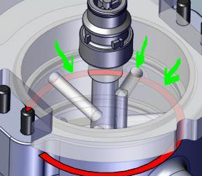
When a part is on top of another one, depending on the camera's orientation, the color of both parts does not blend and any part may appear as being on top of the other one, in an unsystematic manner. Therefore, the rendering is not always as expected.
|
- Shininess
- Specifies how reflective the actor is.
|
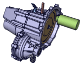
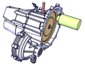
- Emission
Specifies the intensity of reflected light.
|
| | Low emission
| High emission
|
|
- BOM ID
- Specifies the bill of materials (BOM) identifier as appears in callouts. You can assign BOM IDs automatically from the BOM workshop.
|
| Texture | - Show
- (Not available for all
Environment effect -
Type values.) Applies a texture to the actor.
|
- Map path
Specifies the file path of the texture image.
|
- Transparency
Makes the texture image transparent so actors below it are visible.
|
- Projection mode
- Specifies how the texture image is projected onto the actor:
|
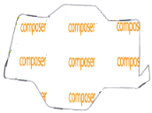
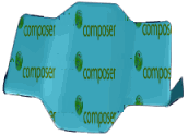
- Blending (modulate)
Mixes the color and transparency of the texture with those of the textured actors. They are affected by the lighting of the scene. When disabled, the texture is not affected by the actor material or scene lighting.
|
| | Disabled
| Enabled
|
|
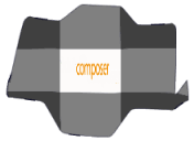
- Mosaic (repeat)
Repeats the texture image to fill the available space.
|

| | Disabled
| Enabled
|
|
- Ratio height/width
Stretches the image, changing its aspect ratio.
|
- Scale
Specifies the displayed image size.
|
| Environment effect | - Type
- Applies a material texture:
-
None (no environment effect)
-
Chromic
-
Metal
-
Metal brushed
-
Plastic
-
Glass
-
Glass plastic
-
Chromic II (with color)
-
Gold
-
Aluminum
-
Satin
Note:
Selecting Gold, Satin, Aluminum, Glass or Chromic disables the Color, Shininess and Emission properties from the Properties pane.
|
- Map path
Specifies the file path of the texture image.
|
| Outline | - Width
Specifies the width, in points, of actor outlines (sharp edges, construction edges, and smart
outlines).

|

|
| Width = 1
Color = black |
Width = 3
Color = red |
|
- Color
- (Available when
Same outline color for all actors (Document Properties - Viewport) is selected.) Specifies the color of actor outlines (sharp edges, construction edges, and smart outlines). When
Same outline color for all actors is cleared, outlines are based on actor colors.
|
- Minimum angle
Specifies the minimum angle between two face planes that defines a sharp-edge outline. Smaller values produce more lines.

|

| | 5
| 100
|
|
| Animation | - Path
Specifies the type of animation path between location keys:
-
Linear - Creates straight paths.
-
Custom - Creates configurable curved paths (Bézier curves). To change the path shape, drag the blue anchors.
-
Smooth - Creates curved paths (cubic Hermite splines). Path, rotation, and speed are optimized to produce smooth animations. For best results, define at least four keys because the path at any point is calculated using the two preceding and the two following keys.
|
- Time function
- Specifies how transformations are applied during a time period:
-
Linear - Applies transformations uniformly.
-
Sine - Applies transformations nonlinearly. For example, an actor moves more slowly at the beginning and end of a path than in the middle.
|
| Kinematic link | - Link type
- Specifies the kinematic link type:
-
Free - Specifies no kinematic link. The actor can move freely.
-
Pivot - Allows rotation in one direction as specified by
Link axis.
-
Spherical - Allows rotation in all directions.
-
Linear - Allows translation along the
Link axis.
-
Rigid - Disables all actor transformations.
|
- Link axis (in parent)
- (Available when
Link type is
Pivot or
Linear.) Specifies the free axis.
|
- Limited joints
- (Available when
Link type is
Pivot,
Spherical, or
Linear.) Limits the range of motion.
|
- Rxmin /
Rxmax / Rymin / Rymax
/ Rzmin
/ Rzmax
/ Xmin
/ Xmax
- (Available when
Limited joints is selected.) Specifies range-of-motion limits.
Note:
For Pivot and
Spherical, Rxmin /
Rxmax / Rymin / Rymax
/ Rzmin
/ Rzmax
values must be included within the following range: -180 degrees to 180 degrees.
|
| Geometry | - Area / Volume
- Specifies geometry information read from CAD. These values have no effect on Composer geometry with the following exception: changing area or volume of pipe geometry affects measurement collaborative actors.
|
- Bounding box volume
- (Read-only.) Specifies the bounding box volume for the actor.
|
- Type
- Specifies the geometry type. Composer uses geometry types to determine certain actor behaviors. For example, only
Solid actors can have cutting-plane capping. Possible values are:
-
Undefined
-
Solid
-
Face
-
Pipe
-
Point
-
Curve
-
Construction geometry (fta)
|
- Scale X / Scale Y
/ Scale Z
- Changes the actor size by the specified scaling value. Specify 1.0 for the default size (no scaling).
|
|
Custom rendering
(Available when
is selected)
| - Priority
Sets the priority of the rendering layer. Actors with higher priority are displayed above lower priority actors. The priority affects actors in the 3D scene and in vector output.
In the following example, a priority of 1 is applied to the red baseplate.
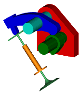
|
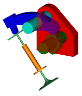
| | Priority=0 | Priority=1 |
Note:
Ghosted actors with high priority can create unexpected effects, such as holes through parts.
|
- Opacity
- Sets the opacity of the rendering layer to show more or less of layers below with higher priorities. For example, if Layer1 is above Layer2 but Layer1 has lower priority, the visibility of Layer2 is controlled by the opacity of Layer1.
|
- Rendering
Sets the rendering mode of the rendering layer:
-
Smooth
-
Smooth outline
-
Technical
-
Flat technical
-
Silhouette
In the following example,
Silhouette is applied to the red baseplate:

|
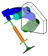
| | Smooth | Silhouette |
|
- Visible lines style for Technical Illustration
Specifies the line style for visible lines in vector output.

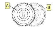
| | Gear A: Solid visible lines
Gear B: Dashed visible lines
|
|
- Hidden lines style for Technical Illustration
Specifies the line style for hidden lines in vector output.

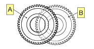
| | Gears A & B: Solid visible lines
Gear B: Dashed hidden lines |
Note:
Gear B hidden lines are visible because its rendering layer has higher
Priority than Gear A.
|
| Event | - Pulse
Specifies the rate at which the actor flashes, indicating an event is defined: -
None - No flashing.
-
200 ms - Flashes every 200 milliseconds.
-
400 ms - Flashes every 400 milliseconds.
-
800 ms - Flashes every 800 milliseconds.
Notes:
-
Composer pulses all actors in the scene at the same rate using the most recently set value.
- In animations, defining a pulse key pauses the animation until the user clicks the actor. Use
the property to define the action when clicking the
actor. If Link is not defined, the actor
flashes only when Design Mode
 (status bar) is cleared. (status bar) is cleared.
|
- Pulse Color
(Available when
Pulse is not
None.) Specifies the flashing color.
|
- Link
Defines the action performed when a user clicks an actor or hotspot in the viewport or in vector image output (see the Technical Illustration - Hotspots tab).
To create an event link: - Click in the
Link field and then click
 . . - In the
Select a Link dialog box, select a link type in the
URL field, specify an appropriate target for that type, and then click
OK.
See Select a Link. - To test the event in the viewport, disable
Design Mode
 (status bar) and then click the actor or hotspot. (status bar) and then click the actor or hotspot.
|
- Pack linked resource
(Available when the
Link property specifies a
file:// URL.) Includes the linked file as part of the Composer document. To omit the file, clear this property and ensure that recipients of the document have the linked file in the same absolute path.
|
| Hatching
(Available when a
Hatch by actor cutting plane property is selected) | - Angle
- Specifies the rotation angle of hatch lines.
|
- Color
- Specifies the color of hatch lines.
|
- Hatch
- Specifies the spacing between hatch lines. To turn off hatching, specify 0.
|
- Thickness
- Specifies the thickness of hatch lines.
|